Bench lathe and box
Object No. 2009/1/1
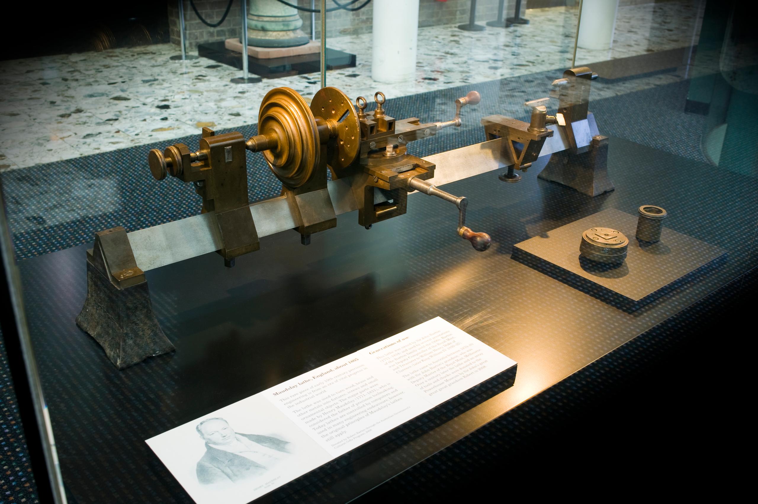
This lathe is an important example of early 19th century precision engineering with a highly significant provenance. The major components of the lathe were made by Henry Maudslay, a British toolmaker who not only introduced the screw-cutting lathe in the late 18th century, but also went on to form a company which played a part in many significant British engineering projects in the 19th century such as the first tunnel under the Thames; and later the company was a principal marine-engine builder. The owner of this particular lathe, Sir John Barton (1771-1834), was reportedly an associate of Maudslay. Barton was the Deputy Comptroller of the Royal Mint in England from 1816 to 1830, and also Secretary and Treasurer to William Henry Duke of Clarence (later King William IV 1830-1837) and after William's accession of the throne held the same position with Queen Adelaide. Sir John Barton was an amateur engineer of some note, and as well as having an interest in lathe work, Barton also engaged with other precision engineering equipment. He owned an engraving machine made some time in the early 1800s, possibly by Maudslay, which produced metal buttons with intricate designs. This machine was the first known of this type. It was brought to Australia in the late 1800s by Barton's grandson, who was the Deputy Master of the Royal Mint, Melbourne Branch (1870-1880s), and the machine - known as the Barton Ruling Engine - was awarded medals at the Melbourne Exhibitions of 1880 and 1888. The Barton Ruling Engine was donated to the Science Museum in England in the early 1900s. The Buttons were mentioned by Charles Babbage (the Powerhouse Museum holds a section of Babbage's Difference Engine No 1 in its collection) in his biography, who was a friend of the Bartons. The donor of this lathe is the great great great grandson of Sir John Barton. The lathe is an example of precision engineering. In the industrial revolution lathes enabled the manufacturing of uniform components, increasing the productivity of manufacturing. Lathes have become very sophisticated and highly precise pieces of equipment used in most engineering endeavours, though the original principals of Maudslay's lathes are still utilised. This lathe is in excellent condition and illustrates this fine engineering clearly. Damian McDonald September 2008
Loading...
Summary
Object Statement
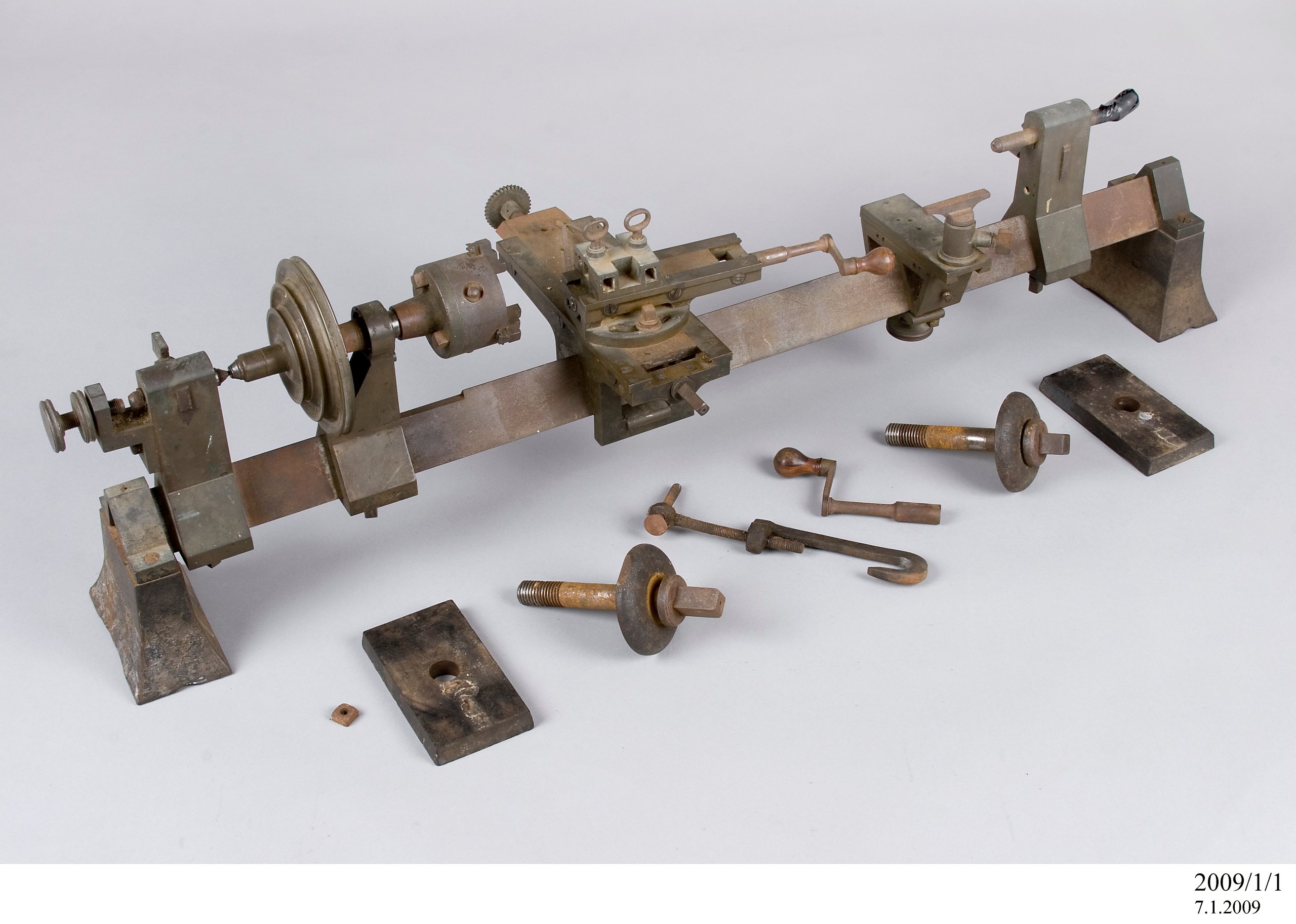
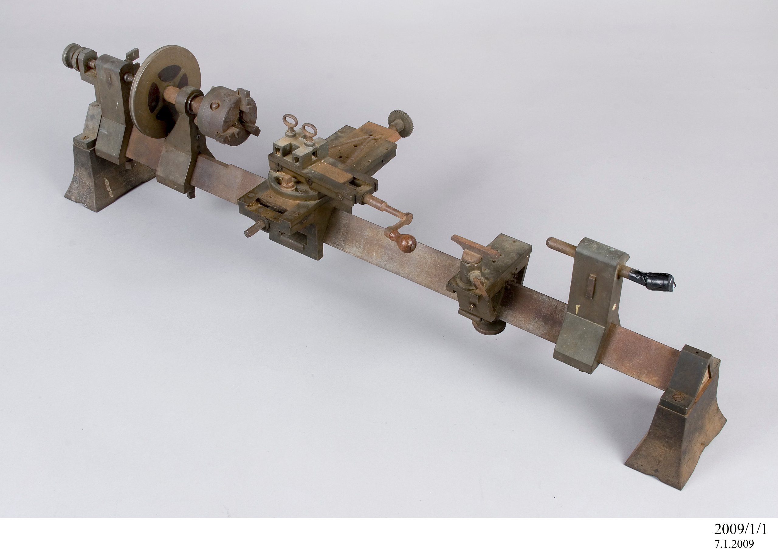
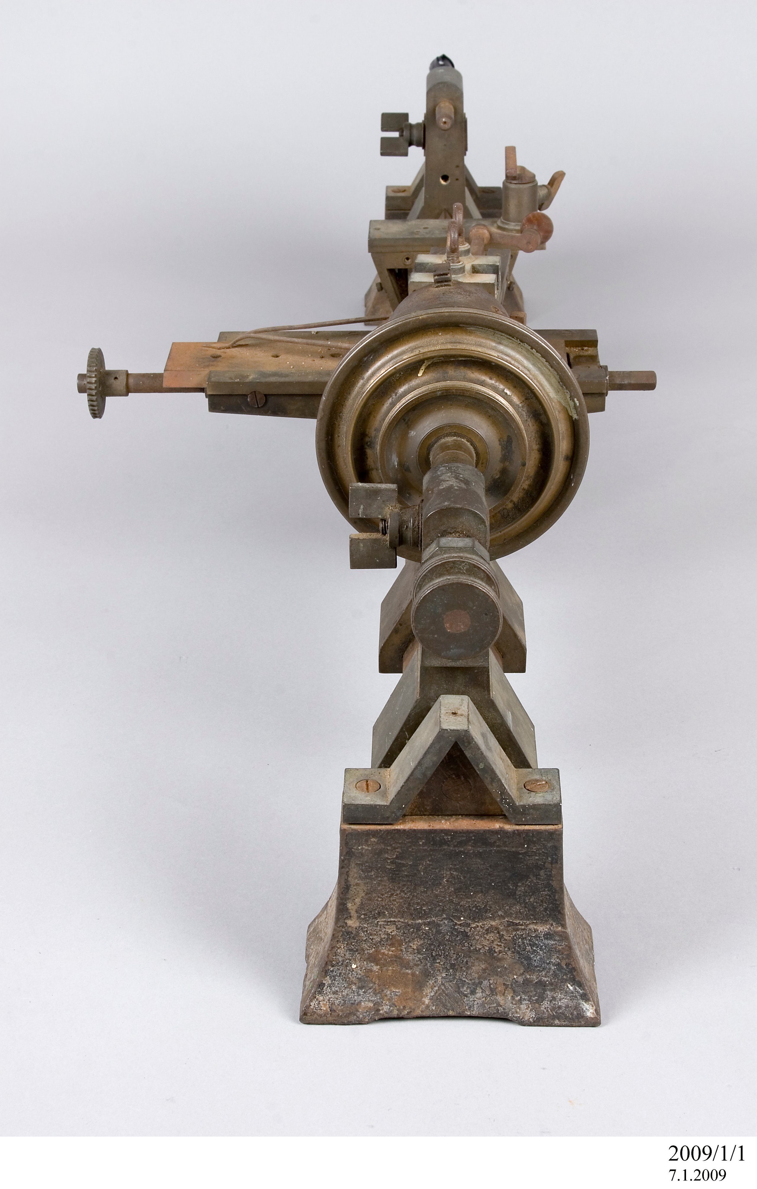
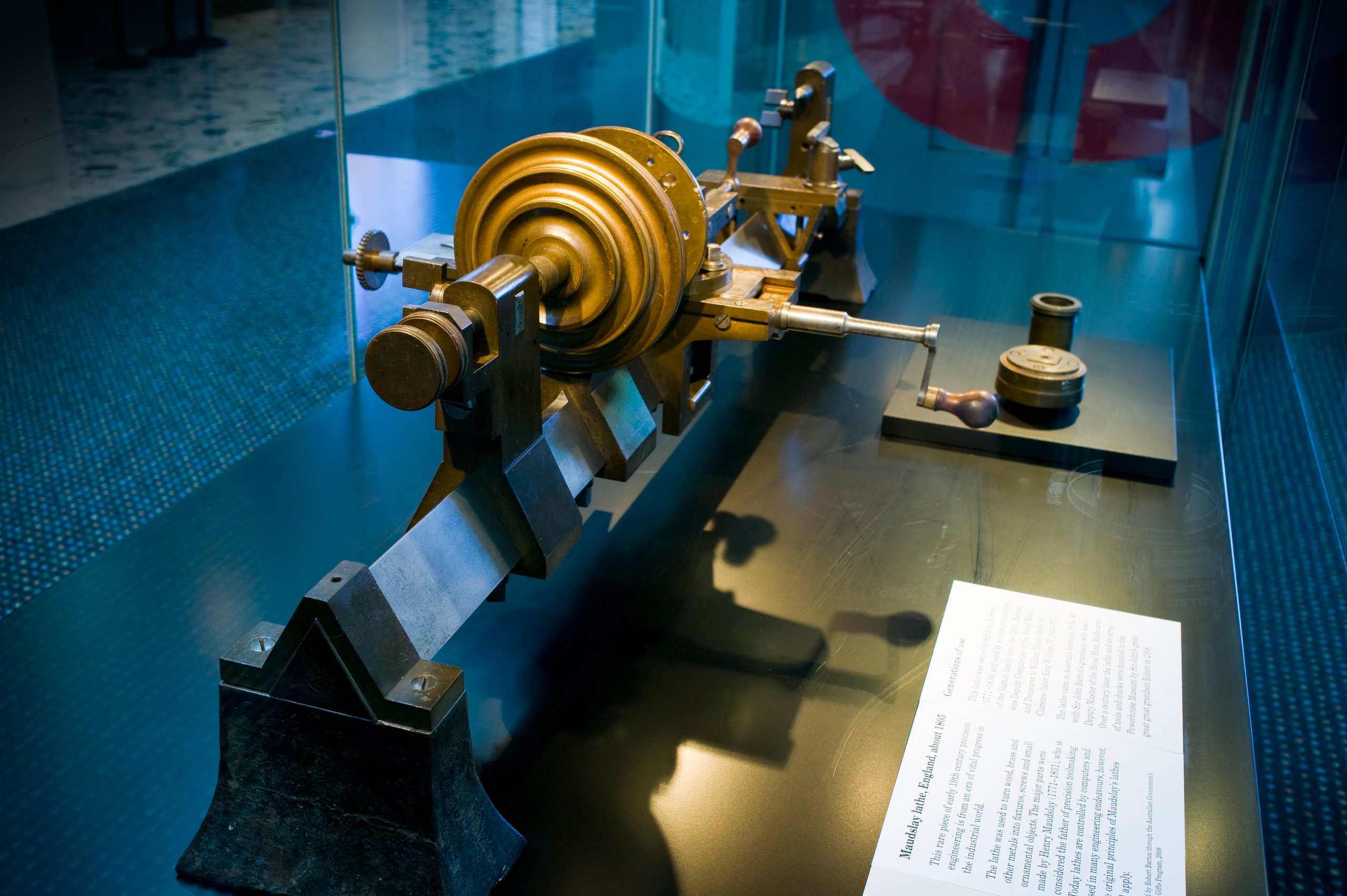
Bench lathe with triangular bar bed, mandrel, tailstock with loose runner, hand rest with one tee, slide rest, attachment for converting lathe to back gear, foot wheel, and box, metal / wood, made by Henry Maudslay, England, c. 1805
Physical Description
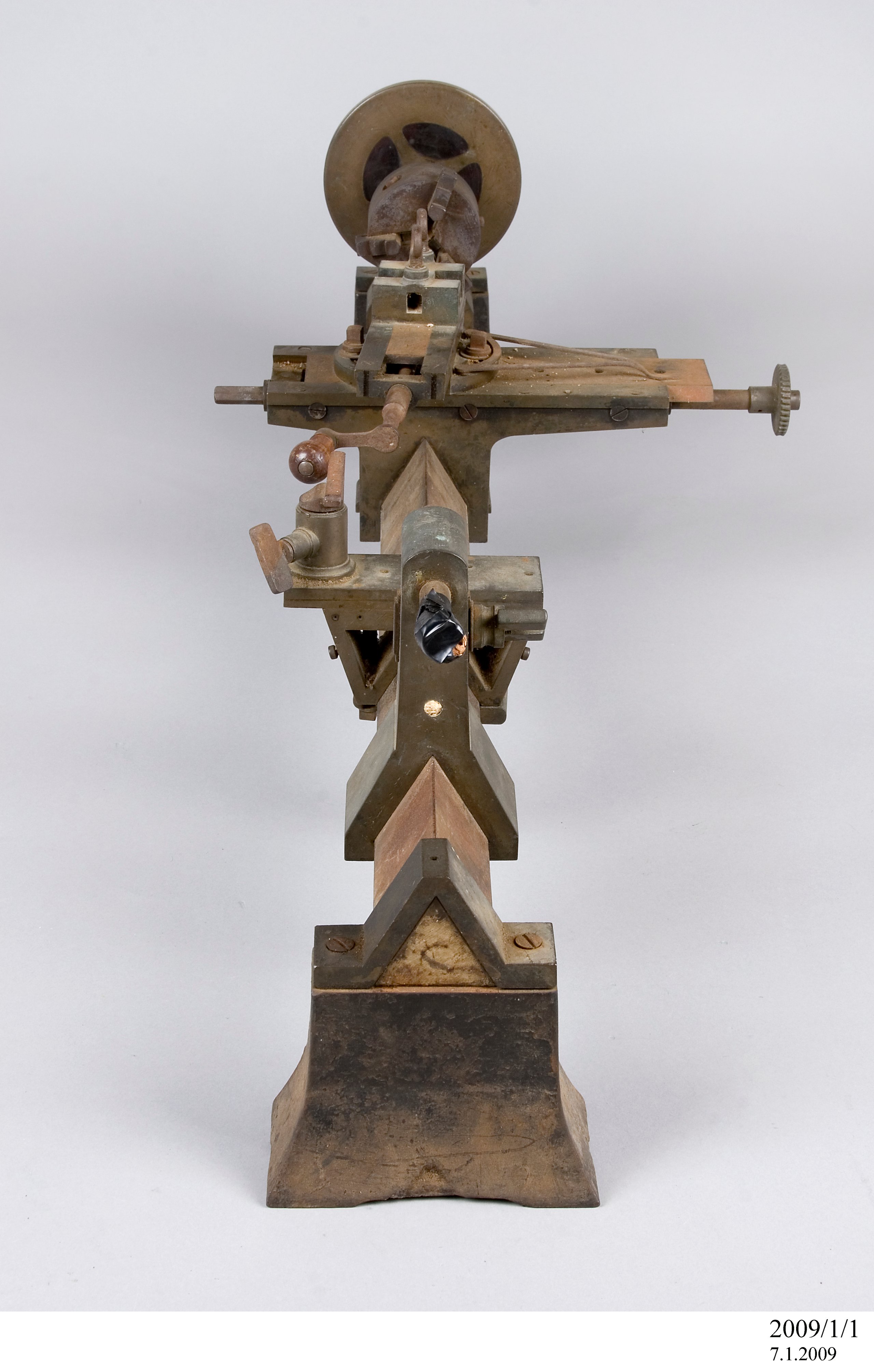
Lathe consisting of various components with transportation box. The bar is made of cast iron. There is a long shallow notch in the bar just to right of neck, a poppit to clear the large chuck or workpiece and scars from cutting off of circular pouring gates or chucking pieces. The poppits for the mandrel are made of bronze. Their style corresponds to that of Lancashire clock lathes (but these are more commonly seen in iron) with mandrel carried between independent poppits fitted individually to the bar. The neck poppit has a steel plug with centre in, on the right face below the collar. The left poppit carries a plain runner for the tail of the mandrel, and a cock is screwed on to bear a screw, with lock nut, which urges the runner up. The runner is clamped in the same way as the tailstock runner. The mandrel and pulley are made of bronze with hardwood filling. No numerals seen. Numbers of divisions not counted. The cone has three steps with round-bottomed grooves suitable for 1/4 inch gut; these were turned round, and have not worn to that shape from vee grooves. Mandrel appears to be steel throughout with double-cone neck. The seat for the pulley is octagonal and tapered. The style of the pulley corresponds closely to that of a headstock signed Maudslay in the Institution of Mechanical Engineers (London). There is a brass sleeve on the tail of the mandrel, part of which has been cut up into a fine helix. The chuck is an American-style three inch three-jaw geared-scroll self-centring chuck, dating probably from the late 19th century. Loose poppit or tailstock has a reversible runner, with male and female centres. The poppit has some empty holes, indicating that other parts were once fitted to it. The Handrest locks to the bar in a way also reminiscent of Lancashire clock lathes: tightening the locking screw to lock the lower part to the bar also draws down a steel dovetail slip through two bolts which locks the slider to the lower part as well. The bronze slider is made up with separate jib pieces screwed or riveted with steel pins. The tee and its binding screw are steel. Several holes drilled into the lower block and into the slider, some tapped, indicate that other apparatus has been mounted to these parts. The slide rest, though unsigned, is undoubtedly by Maudslay and is of his usual pattern. The bronze base casting is clamped to the bed by steel bow nut and keeper. The lower slide has bronze gib pieces both sides which are adjustable, each having three setting-up screws and four binding screws which are numbered and correspond to numbers stamped adjacent to them. The slider is of cast iron. The steel lead screw is let in from above with caps that are flush, each held by two screws. The nut of brass or bronze is divided horizontally; the two parts united by two screws put in from below, and is fixed to the slider by two screws from above. The screw is very fine and extends to the rear about 13.5mm; this was intended to carry wheels for the screw-cutting apparatus with the slide mounted on a right angle extension piece (not present) so that this screw would be parallel to the lathe axis. This end of the screw now carries a brass or bronze worm wheel (36 teeth) 47.5mm in diameter. It was once secured by a cross pin, now absent. This would appear to be intended for an automatic feed to this motion of the rest, using other apparatus that is lost. The slider has six tapped holes on its centre line to receive the centre pin and binding screws of the upper slide. The centre pin is conical and has a slot for a screw driver. The upper slide has a bronze base which is capable of being set round to about 30 degrees each side of right-angles to the lower slide. The steel index mentioned above fits into two holes on the rear flange of this piece. Both gibs (bronze) are movable, secured by four binding screws each, but only the front one is adjustable. The slider is bronze with three sockets for the cutter, cast all in one piece, one socket along and two across, with two steel bow screws to clamp the tool. The steel lead screw is put in from the winch end and held in place by a ring nut sunk into the casting at the other end. The original steel winches for both slides are present. The webs of both are bent. Both have original handles of hard wood (Lignum vitae) with brass ferrules. That for the lower winch has seized tight on its pin. The backgear apparatus comprises two cast brackets that fit on the bed-bar, connected by a rod passing through two holes at the level of the bottom of the bar. The present rod, with its ends shouldered and with left hand threads, appears to be an improvisation. A steel shaft runs in holes above the level of the apex the bar. Between the brackets this carries a pinion of twenty teeth, roughly pinned on. To the left is a wheel fitted on a bush. The spindle is extended to the left and has a tapered square, apparently for a winch. To the right it is fitted with a collar in brass or bronze in which is planted a radial index with pointed end. The point is turned back, but that may be accidental damage. Beyond this is a wooden pulley with a flat-bottomed groove, slightly chipped. The wheel and pinion are of brass or bronze and may have originally belonged to a set of screw cutting wheels associated with the slide rest. The apparatus as a whole does not give the impression of having been a part of the original equipment. The bench stools that support the ends of the bar are rough iron castings, dressed only on their upper surfaces, to each of which the bar is held by a brass or bronze bridge piece, each secured by two countersunk screws. These fine-threaded screws, tapped into the iron, look original, but the tap bolts that screw in from below to secure them to the bench have coarse threads. The holding-down bolts have square heads with circular collars and work through cast iron keep plates. The under sides of the stools are relieved to form four pads at the corners. The footwheel is more recent and improvised. There is an iron footwheel with five straight arms and three vee grooves. The grooves and the faces of the rim have been turned; some chattering is evident on the faces, suggesting that the wheel may be fairly early, or otherwise that it was turned using an improvised set-up. The boss is not turned outside but is bored and a key way is cut. This wheel may be original, but it is rather small and light by the usual standards. The crank is bent from a round bar. The seat for the wheel and the neck for the pitman are turned. It runs in solid plummer blocks which are certainly not original. The pitman appears to be improvised, as is the treadle. The box is of wood with metal fastenings. It is the original box in which the lathe was transported by ship from England to Australia.
DIMENSIONS
Height
370 mm
Width
290 mm
PRODUCTION
Notes
The lathe appears be made by Henry Maudslay (1771-1831), a British precision tool-maker who manufactured and perfected some of the world's earliest metal lathes. It is very similar to the designs for bench treadle lathes by Maudslay appearing in 'Rees Cyclopaedia' reproduced in 'Henry Maudslay and the Pioneers of the Machine Age' by Cantrill and Cookson.
HISTORY
Notes
The lathe dates from the early years of the 19th century, and was owned and used by Sir John Barton. John Barton was the Deputy Comptroller of the Royal Mint in England from 1816 to 1830, and also Secretary and Treasurer to William Henry Duke of Clarence (later King William IV 1830-1837) and after William's accession to the throne held the same position with Queen Adelaide. Sir John Barton is known to have been an associate and client of Henry Maudslay, as well as others in the circle of engineers and amateurs involved in the development of precision machining, for which London became a centre at the time. Other people in the group include Bryan Donkin, Joseph Clement, Joseph Whitworth and Charles Babbage. John Barton famously at the time produced a ruling engine for creating 'Barton's Buttons': metal discs which had perhaps the earliest known diffraction grating scribed on them which caused beautiful optical effects on the surface. Charles Babbage refers to carrying a set with him in his biography. The lathe passed to Sir John Barton's grandson who came to Australia to take up a position at the Melbourne Mint. The lathe has been used by successive generations of Bartons in Australia.
SOURCE
Credit Line
Donated through the Australian Government's Cultural Gifts Program by Robert Barton, 2008
Acquisition Date
12 January 2009

Copyright for the above image is held by the Powerhouse and may be subject to third-party copyright restrictions. Please submit an Image Licensing Enquiry for information regarding reproduction, copyright and fees. Text is released under Attribution-Non Commercial-No Derivative licence.
Image Licensing Enquiry
Object Enquiry