Vickers No.1 anti-aircraft predictor
Object No. 2010/1/285
This object is part of a collection relating to the history and development of calculating devices assembled by Assoc Professor Allan Bromley of Sydney University, comprising mathematical instruments, slide-rules, mechanical and electronic calculators, electronic analogue computers, computer components, kit computers, education computers, and associated ephemera. Allan Bromley was a lecturer and researcher at the University of Sydney Basser Department of Computer Science from 1978 until his untimely death in August 2002. He specialised in Computer Architecture, Computer Logic and in particular the History of Computing. He was regarded as the world authority on Charles Babbage's Calculating Engines (instigating the building of the Difference Engine No.2 at the Science Museum London) and the Antikythera Mechanism and had extensive knowledge of calculators, analogue computers, logic, stereopsis, totalisators, clocks and time keeping and mechanical engineering.
Loading...
Summary
Object Statement
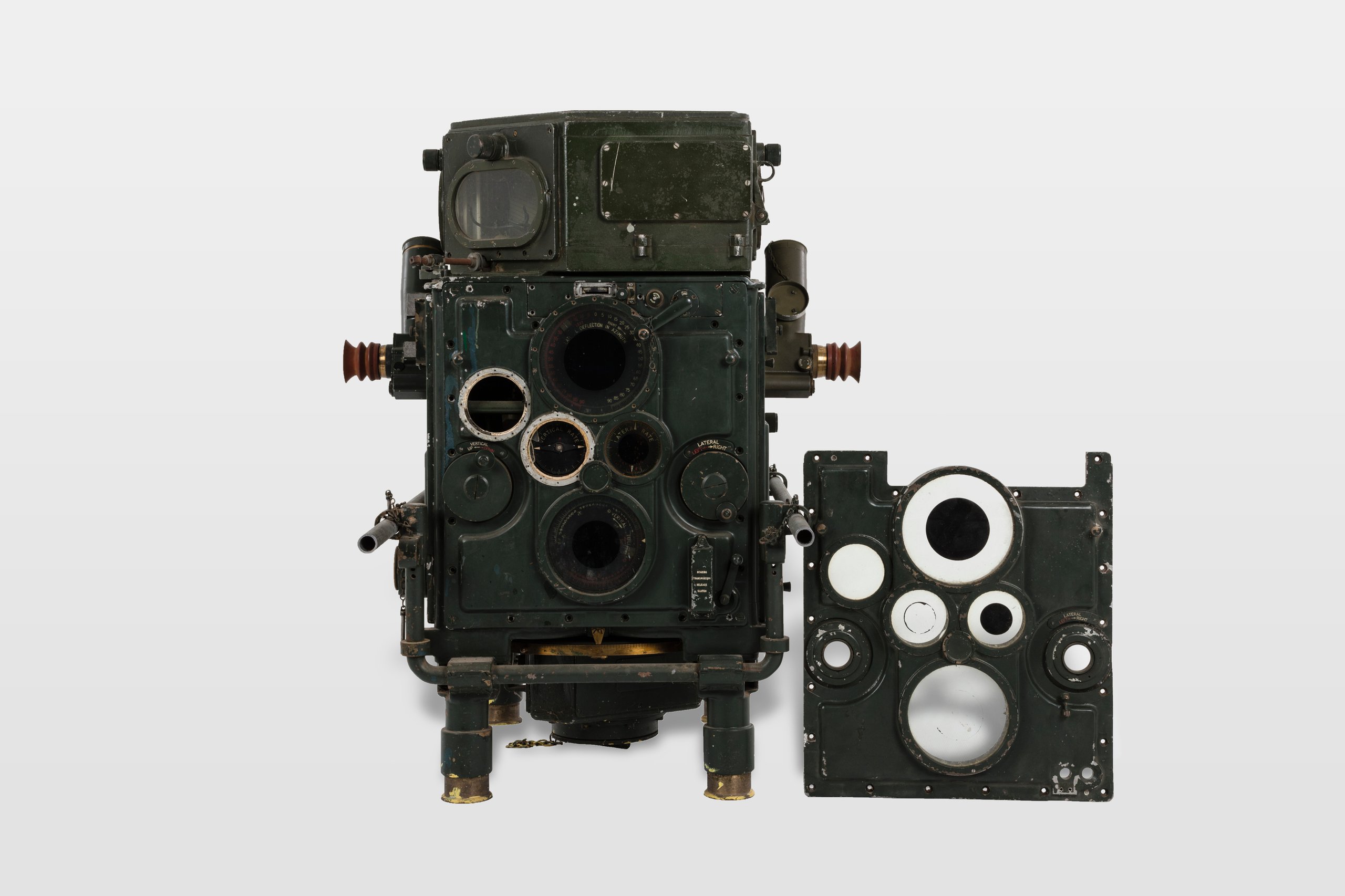
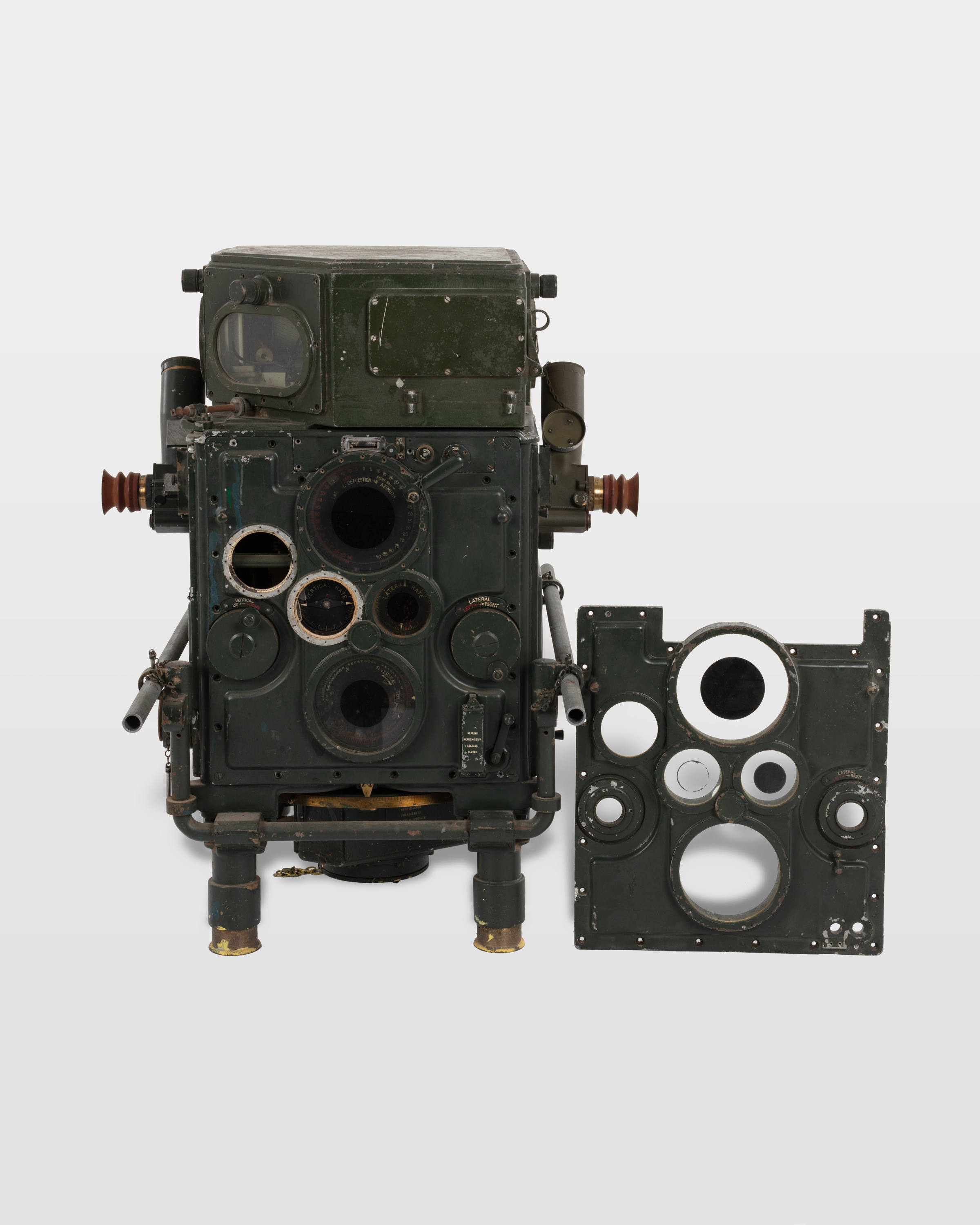
Analogue computer, Anti-Aircraft Predictor, Vickers No.1 Mk III, metal / glass, designed by Vickers Limited, England, 1924, made by Sperry Gyroscope, United States of America, 1942
Physical Description
The Vickers Mk III Anti-Aircraft Predictor is an analogue computer designed for plotting the current position, course and speed of incoming aircraft as well as calibrate and aim anti-aircraft guns. The device consists of two metal cases, painted in military dark green, with the smaller bolted on to the top of the main section. The upper section, has a panel of the right, marked 'COMPUTER HEIGHT A.A. No.1 MK I / GEC / 1942 / REG No 730 / O.S.19.M.A', and consists of a pipe input with a spring loaded cap and a series of, glass covered, ovular windows on the sides for viewing the inner workings of the computer which include a number of wires, small lights and a horizontal cylindrical calculator. Around the top edges there are a number of screw caps, which house small light bulbs. The main body is square and rests on four solid, cylindrical, feet and can be divided into four panels, each serving a different purpose. The front panel, has a plaque in the centre, inscribed with 'PREDICTOR 3. 7 INCH H.A. No1 MK III / THE SPERRY GYROSCOPE Co Ltd 1941 / No 231', which can be opened to reveal the inner workings. Above this are two circular winders labelled 'TIME & FUZE' and 'TANGENT ELEVATION' as well as a number of gauges and small dials for 'WIND DIRECTION' and 'GUN HEIGHT'. The back panel is similar to the front and contains a series of circular dials, knobs and winders, in a diamond shape, inscribed with, 'LATERAL DEFLECTION IN AZIMUTH', 'VERTICAL RATE', 'LATERAL RATE' and 'VERTICAL DEFLECTION'. The two side panels each consist of a central telescopic sight, which can be adjusted along a 90 degree gauge, and have a metal cap, red rubber eye protector and an adjustable focusing gauge made from brass. The left side panel is used for adjusting bearing and features a circular slide on the right, indicating height in 1000 increments and a 'TRANSMITTED BEARING' gauge below, which can be adjusted using two rotating levers for normal and fast traverse. The right panel, used for calculating and adjusting elevation contains a small window for viewing inside the device and a circular gauge marked, 'QUADRANT ELEVATION' below. Positioned under the main body is a brass, 360 degree, disc, that is used to determine the correct positioning for the anti-aircraft guns. A spare panel, which can be placed over the back side has four glass gauge covers and a series of cut outs to slot over the dials and knobs.
HISTORY
Notes
Military analogue computers go back to naval gunnery before World War I. At that time, because the speed of ships is small compared to the velocity of shells, in general only simple linear calculations would be required, and the main problem was to keep continuous track of the range and bearing of the target. In response to the substantial military threat from aircraft, there was a rapid development of gunnery computers in the 1920s. The basic anti-aircraft problem is straightforward. The aircraft is tracked, using instruments to determine its present position, course and speed. The course is then extrapolated to derive the position of the aircraft when the shell reaches it. In practice the problem is more complex, however, because the battery has to aim and time the shell to explode within ca. 10 metres of the aircraft, which might travel a distance of at least one and a half kilometres during the flight of the shell. The time to locate the aircraft, set up the calculation and to start firing has to be short, ca. 30 seconds; thereafter the computer had to continue to provide updated firing data to the guns. It would compute the position of the aircraft at the instant of the arrival of a shell, taking account of the direction and speed of the aircraft and the shell, as well as the wind speed. In conjunction with a telescopic identification unit and a height and range finder, the predictor would control the guns of the anti-aircraft batteries. The telescopic identification instrument consisted of two sets of eyepieces placed at either end of a bar, which was placed on a tripod. The spotters - often women - would look into the eyepieces to locate an aircraft and call the range and bearing to the height and range finder crew, who could then more accurately pin-point the location of the aircraft. The spotters had received intensive training in aircraft identification in order to ensure that they correctly distinguished friend from foe. The height and range finder instrument was more sophisticated. It consisted of two telescopes placed in a long-base tube (for example, the Barr & Stroud Finder was 5.5 m long). The operators looked through the eyepieces and pin-pointed the aircraft, noting the height and range, and sent this information to the predictor. The predictor instrument would calculate how far in front of the aircraft the grenade should explode to knock the aircraft off course, taking account of the speed as well as the information received from the height and range finder. The crew would look through the eyepieces and see a small image of the aircraft and turn dials to keep the image in place, and as soon as they were on target, the information would automatically be fed to the guns. The first successful predictor was designed by the English armament company Vickers in 1924 and entered service in 1928. During World War II, it was also made at the Munitions Factory at Maribyrnong, Victoria, to guide 3" and 3.7" guns. An example of this mechanical real-time computer for controlling anti-aircraft fire belongs to the Australian Computer Museum Society (ACMS). To achieve the necessary accuracy, the Vickers predictor used a polar system for pointing co-ordinates. A number of linkage mechanisms were used, as well as disc-and-ball integrators. The operators would enter deflections to keep the dials and the equations balanced and to enter ballistic data by following curves on drum charts. An anti-aircraft predictor made by the American Sperry Gyroscope Co. in the early 1930s used Cartesian co-ordinates. This company's first commercial success was with the gyrocompass for ships, an instrument which was able to transmit the position of the spinning gyro without interfering with its motion. By 1920 the company had installed it on more than 700 ships worldwide, both military and commercial. After WWII, mechanical gunnery computers continued to be developed and elaborated into the 1960s and beyond. They remained in active military service well into the 1970s. Analogue calculation devices yielded only slowly to electronic digital computers. The main reason for the demise of analogue devices was the gradual replacement of guns by self-guided weapons, such as missiles, which did not need accurate aiming systems, albeit that the missiles themselves generally contained analogue guidance systems. In summary, while mechanical analogue computers played only a small role in scientific developments, for some 50 to 60 years they played a wide and dominant role in military computing.
SOURCE
Credit Line
Donated through the Australian Government's Cultural Gifts Program in memory of Associate Professor Allan Bromley, 2010
Acquisition Date
20 January 2010

Copyright for the above image is held by the Powerhouse and may be subject to third-party copyright restrictions. Please submit an Image Licensing Enquiry for information regarding reproduction, copyright and fees. Text is released under Attribution-Non Commercial-No Derivative licence.
Image Licensing Enquiry
Object Enquiry