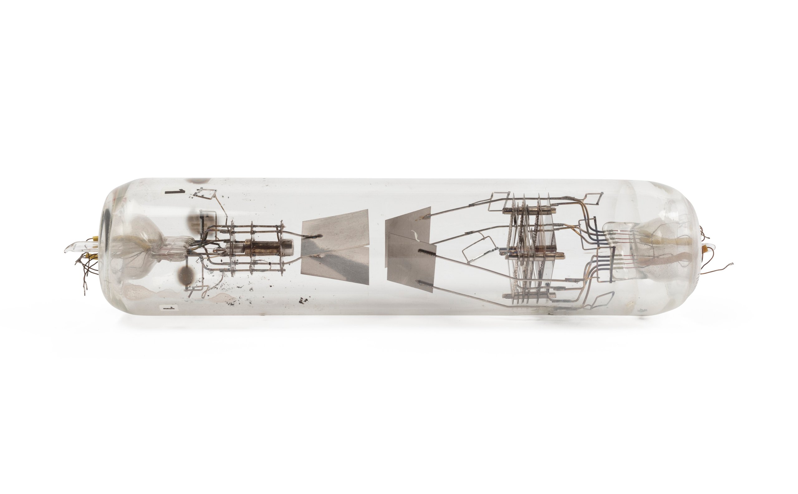
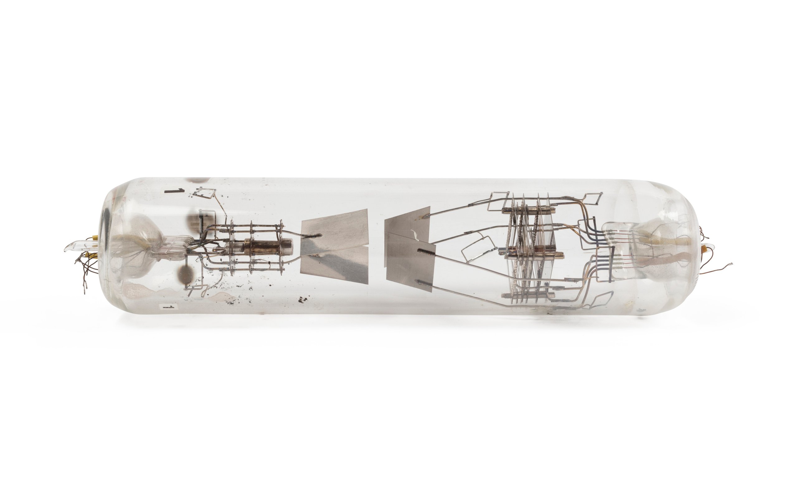
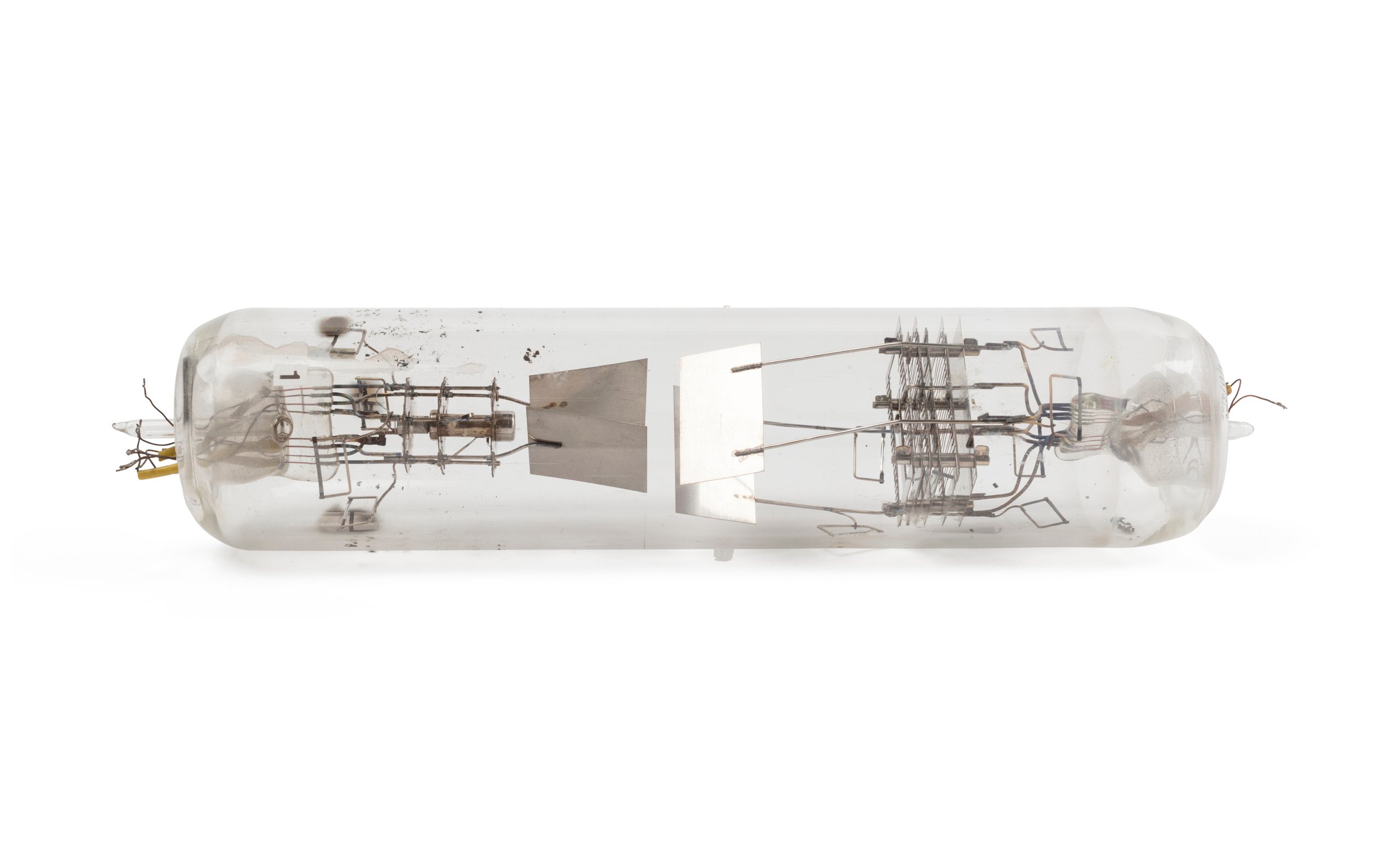
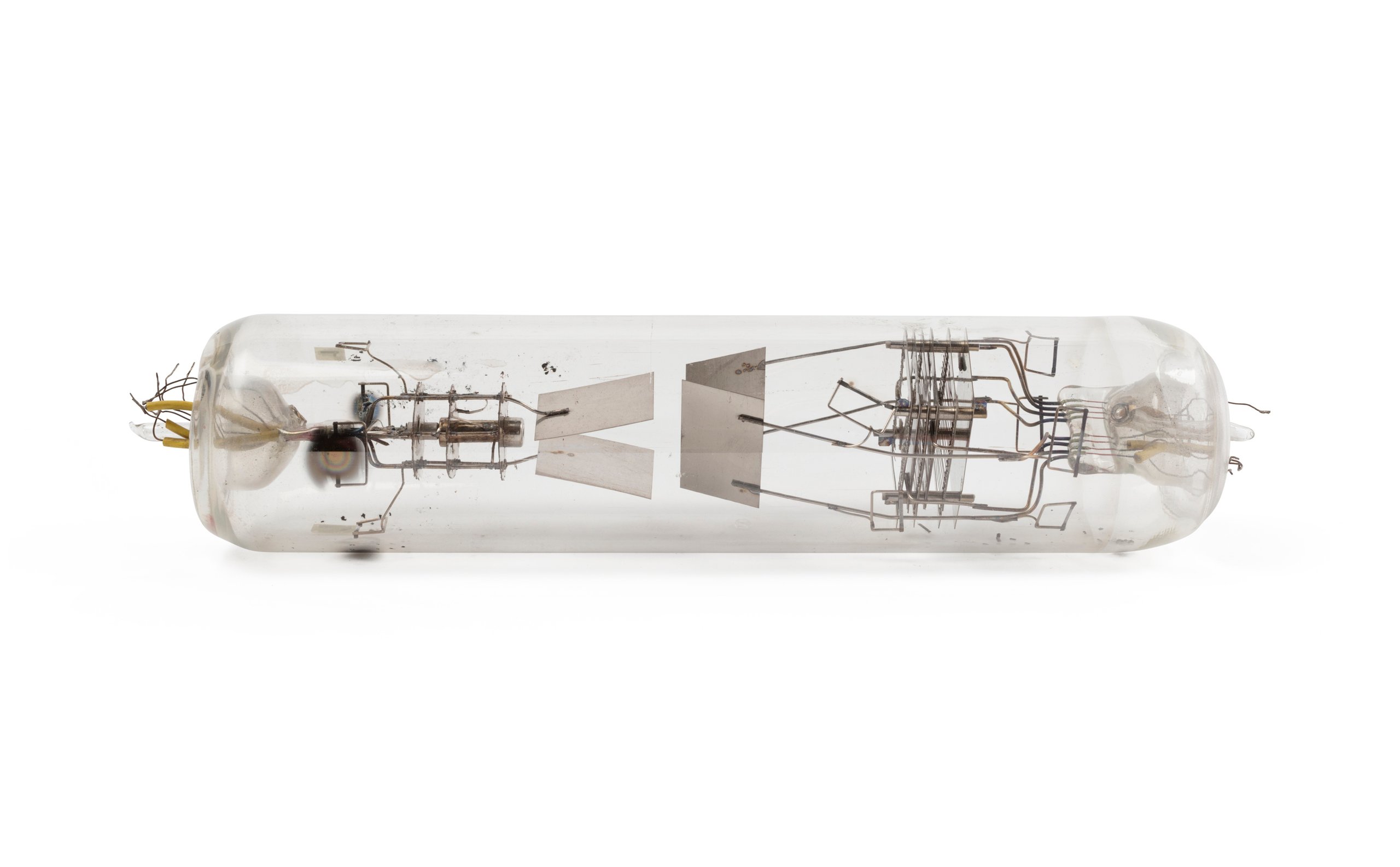
Number 1 from electronic vacuum tube decade (scale-of-ten) counter
Object No. 2014/12/1
This tube is part of a series of tubes developed for a CSIRO research project that culminated in 1951, in a decade counter that could count from 0 - 9999 pulses (or oscillations). It is an example of the first of the series of tubes made by hand in the CSIRO Electrotechnology laboratory at the University of Sydney to designs developed experimentally by David Hollway. Hollway describes it as being "used to test the principle of setting up stable positions of an electron beam by feeding back the beam current to control the voltages on the deflector plates." A number of the tubes were made and the version that Hollway demonstrated at the 1951 Exhibition of Scientific Instruments in Melbourne had four digits. This tube and other objects donated by David Hollway represent the first attempt to develop a single vacuum tube electronic counting device that was also fast enough to record the frequency of high speed events such as the signals output from an ionization chamber during experiments in nuclear physics. Although there were several existing electronic counters, having been originally developed by Wynn-Williams in 1931, they consisted of considerable numbers of vacuum tubes of standard design. As Hollway notes: "In 1947, when the counter tube project was proposed, electronic counters were used chiefly for nuclear research and some electronic instruments. Each scale-of-ten required at least four twin triode vacuum tubes, or pentodes and a number of passive components. For each decade, 10 lights, or a meter with a scale marked 0-9, was needed to display the count. A gas-filled counter tube was in production overseas but was limited in speed." [Hollway's notes] This new design represents an early attempt to integrate the multiple component functions of existing counters into a single electronic device. It used a complex set of components to respond to (count) a sequence of electronic pulses, hold (store) the current count and display it. A carryover signal was also generated to allow a set of the devices to count to at least four digit numbers (0-9999). The display was an additional aspect of the accumulation process in which the currently stored value (from 0-9) was presented as a fluorescent figure on the end of the tube. Previous electronic counters used a meter or a set of separate lights to indicate the current count. The development process was also significant in its use of simulation techniques and analogue computing to confirm the path of the electron beam under the effect of the deflection components proposed for the device. This simulation process itself resulted in the publication of several important papers. [see below for references] The project ran from 1947 to 1951 and had garnered interest from overseas; however it was abandoned due to the recent development of transistors for electronics and the recognition that they would soon replace vacuum tubes in high speed electronics. Literature references: Regarding the decade counter: Nature, vol.6, p.856, May 27, 1950. Electronics, May, 1952, pp.152-154 Australian Journal of Physics, vol.6, no.1, March 1953, pp.96-115. Regarding the theory and simulation of electron flow: Australian Journal of Scientific Research, A, vol.5, no.3, 1952, pp.430-436. Australian Journal of Physics, vol.8, no.1, 1955, pp.74-89. Proc. Inst. Electrical Engineers, vol.103, part B, no.8, 1956, pp.155-165. Jnl. British Inst of Radio Engineers, vol.24, no.3, 1952, pp.209-211.
Loading...
Summary
Object Statement
Electronic vacuum tube, decade (scale-of-ten) counter, Number 1, glass / metal / plastic, designed by David Hollway, made by the CSIRO Division of Electrotechnology, Sydney, New South Wales, Australia, 1947
Physical Description
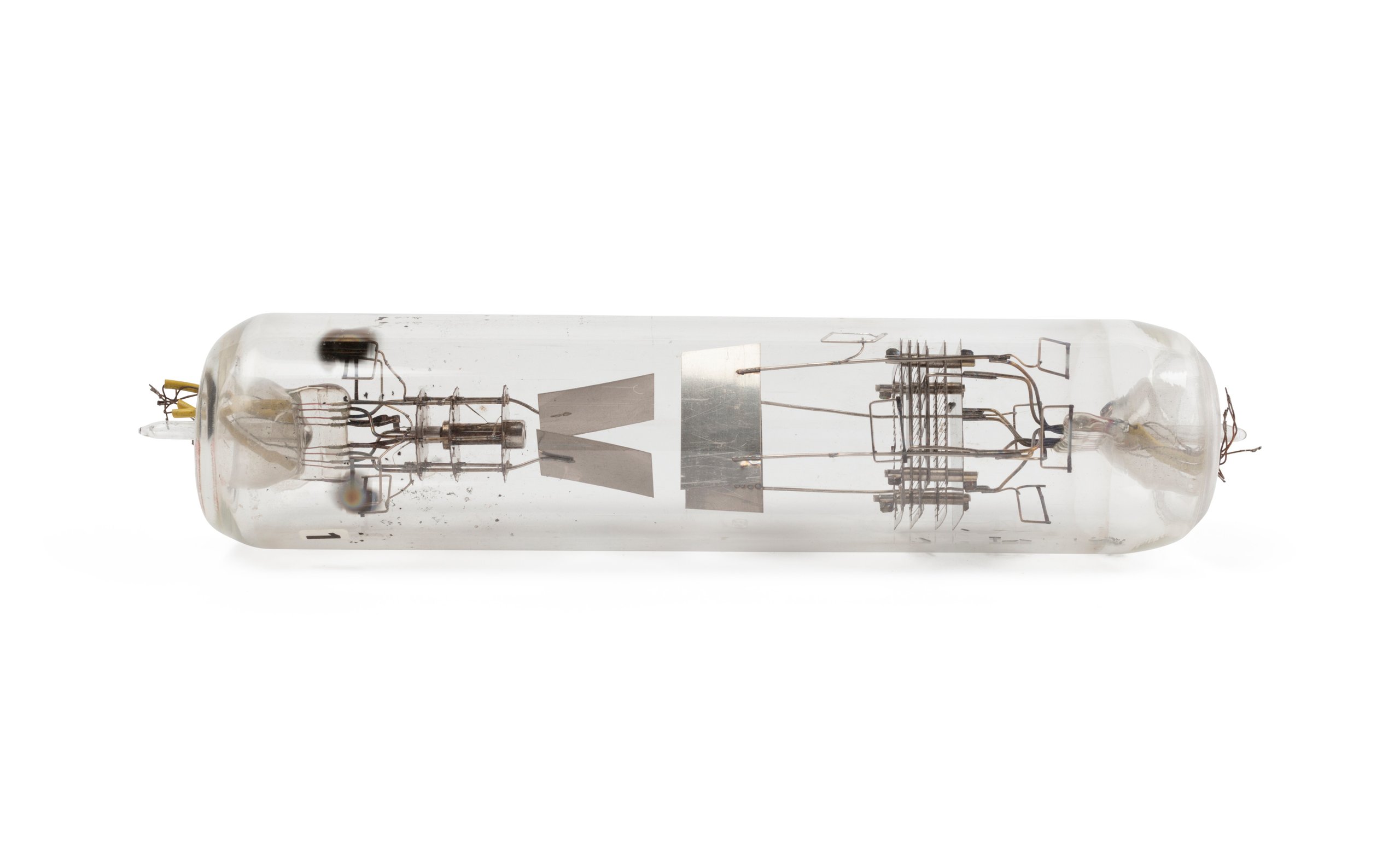
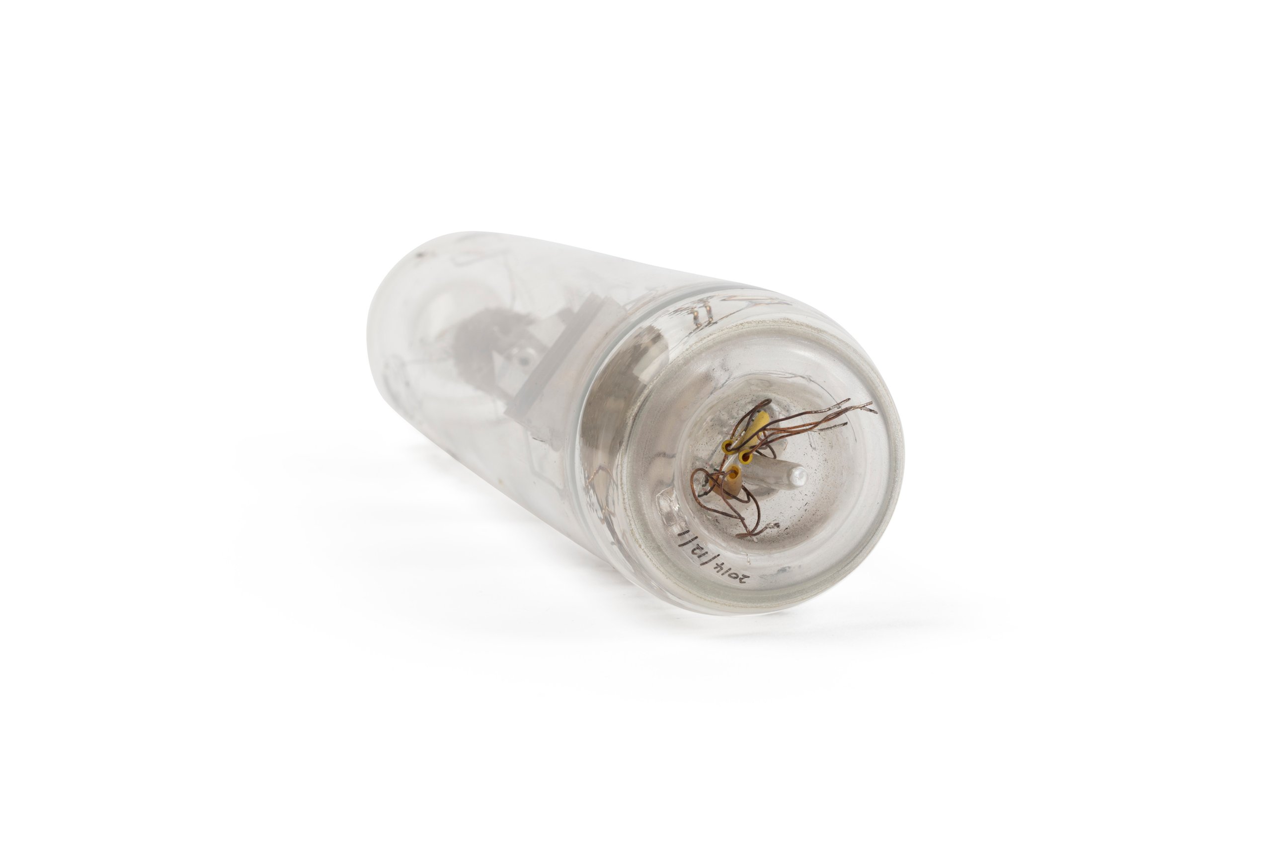
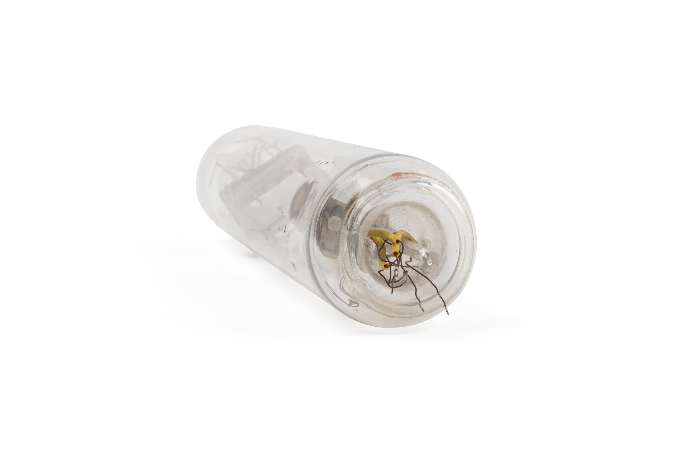
This vacuum tube is made from hand blown glass and contains within the tube, an assembly of metal parts consisting in an electron gun or cathode, a set of grids for controlling the secondary emissions from the beam and a set of deflection plates for controlling the projection of the electron beam from the cathode.
DIMENSIONS
Diameter
65 mm
PRODUCTION
Notes
Handmade at the CSIRO Division of Electrotechnology on the grounds of Sydney University, in June 1947. The final version of the counter tube is a vacuum tube of some 15cm in length by 3cm in diameter consisting in an electron gun (or cathode), a cylindrically arranged set of deflection plates and a series of carefully cut and folded electron beam masks, called collectors, which combine to guide the beam towards a numeral mask with the numbers 0 - 9 cut into it. The electron beam directed (deflected) through one sector of the numeral mask then projects a number on to a fluorescent coating (a phosphor) on the inside of the end the glass bulb. The deflection of the electron beam is controlled by the relative values of the potential (voltage) on each of the five deflection plates. This potential is determined by the interaction of the beam current, the positive part of the input signal, the existing potential on each of the five deflection plates and the potential of the collectors, thus guiding (deflecting) the beam through 2 x five stable states. The potential on the collectors feeds back onto the deflection plates and this arrangement maintains the beam pointing in the current direction until a new positive pulse at the input causes the beam to be re-deflected into the next adjacent stable position (half way between two adjacent deflection plates), thus pointing it through the next numeral mask and onto the phosphor in the end of the bulb. When the beam is directed to the final position on the next input pulse it is returned to the starting state and a carryover pulse is issued which triggers the count in the second tube incrementing its position until it too reaches the carryover state and triggers the increment of the next digit in the set.
HISTORY
Notes
Hollway writes of the project: "Contributors to the Counter Tube Project "In May 1947 the proposal to develop a single vacuum tube which would count electrical pulses, or waves, in the scale of ten, was suggested to the Chief of the Division of Electrotechnology, Dr. D. M. Myers, by D. L. Hollway and A. M. Thompson. Myers was enthusiastic. (Later, when Myers left to become Professor of Electrical Engineering at Sydney University, Mr F. J. Lehany became Chief of the Division of Electrotechnology and continued support for the project.) "It was decided that the design to try first would use an electron beam which could be locked into a number of stable positions, denoting the digits 0-9. Each position would be held by dividing the beam current so as to produce the required voltages on deflecting electrodes. "Thompson prepared a drawing of the X-Y design (tube number 1) and Hollway one of the secondary emitting version (tube number 2). But before these were started, 3 or 4 simple tubes to test electron guns and secondary emitting electrodes were constructed. "These tubes were made in the CSIR Division of Radiophysics Valve Laboratory, situated in the Electrical Engineering Department of the University of Sydney, under the supervision of Professor R.E. Aitcheson. "The initial tests showed some promise, but it was clear that a great amount of work would be needed to design and develop a successful counter with the speed, stability and other characteristics essential to interest manufacturers. "In 1948, Aitcheson left to spend a year or so at Bristol University, so Myers arranged with Dr. Bowen, Chief of the CSIR Division of Radiophysics and Professor Madsen (Professor of Electrical Engineering at Sydney University) for Hollway (who had experience in vacuum tube development and manufacture) to move to the Electrical Engineering Department and take over supervision of the Valve Laboratory and develop the counter. As that laboratory consisted of only two or three very able and experienced people working on Radiophysics projects, little supervision was needed and he was able to work almost full time on the counter tube. "The chief problems were discovered almost immediately. For example: to achieve the necessary speed, a high perveance (high-current at a low voltage) electron beam was needed. But, unlike the high-voltage beams in cathode ray tubes, dense, low-voltage beams tend to blow themselves apart, and cannot be focussed into a small spot after travelling far from the focussing lens. This restricts the path length, and therefore the sensitivity of the deflector system and explains the complex shape of the deflector electrodes. Similar constraints govern the collector design and other electrodes. "In finding a balance between these conflicting requirements, Hollway originated designs and tested models in the electrolytic tank (an analog computer for tracing electron paths) and electrode systems in a demountable vacuum station. "The small and intricately shaped electrodes were made and assembled with great skill and accuracy by Mr. H. Flood, who worked on the project full-time. The expert glassblower (whose name, unfortunately, I do not have recorded) made the bulbs and the special, 12-pin, powdered-glass bases. Mr. A. James pumped and processed the tubes. "All these people contributed to the development of the successful counters made in 1949/1950. ... [T]his stage in the counter tube development coincided with the arrival of transistors. It became clear that transistors soon would take over low-power functions such as counting, and the project was terminated."
SOURCE
Credit Line
Gift of David Hollway, 1999
Acquisition Date
28 January 2014

Copyright for the above image is held by the Powerhouse and may be subject to third-party copyright restrictions. Please submit an Image Licensing Enquiry for information regarding reproduction, copyright and fees. Text is released under Attribution-Non Commercial-No Derivative licence.
Image Licensing Enquiry
Object Enquiry