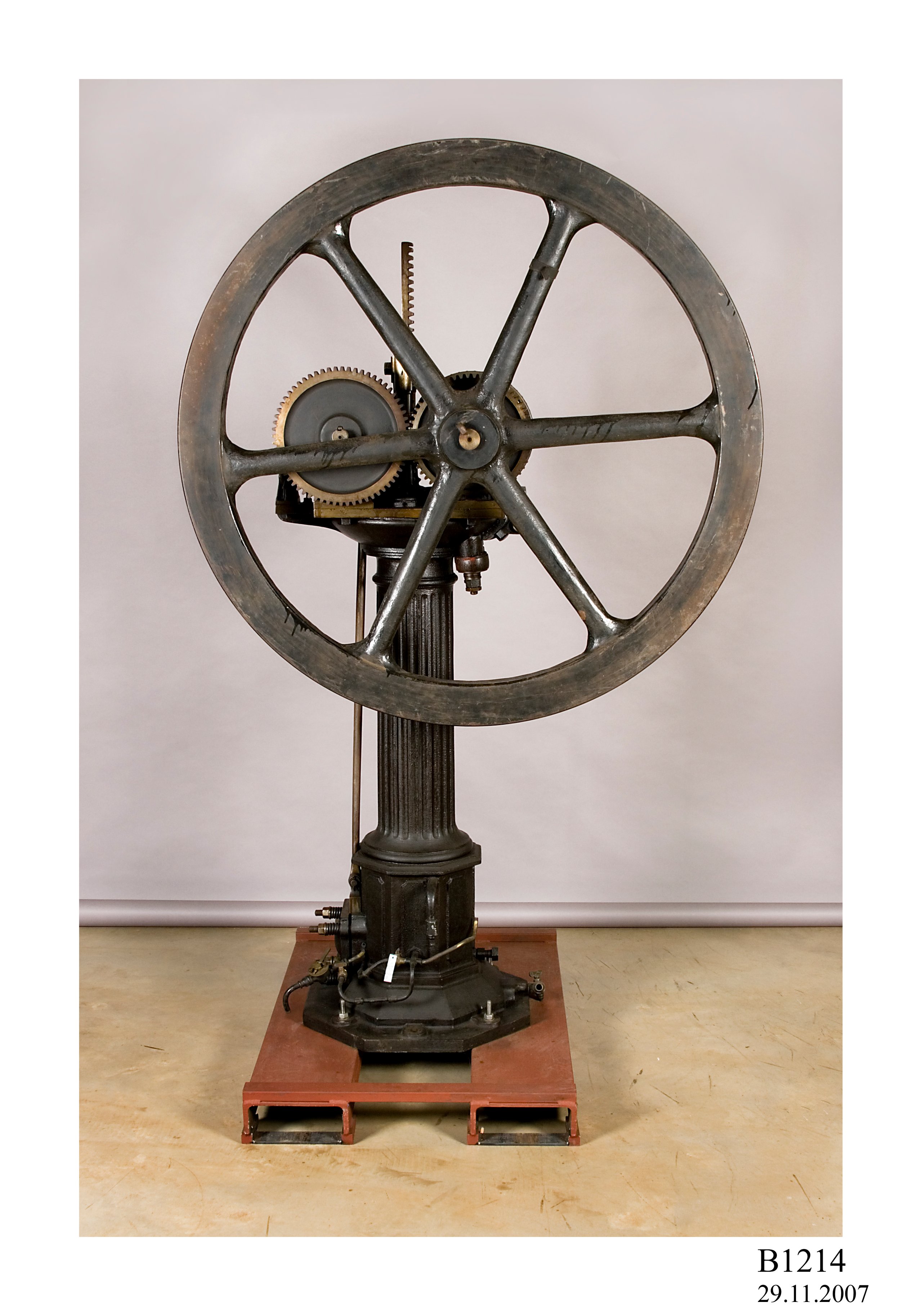
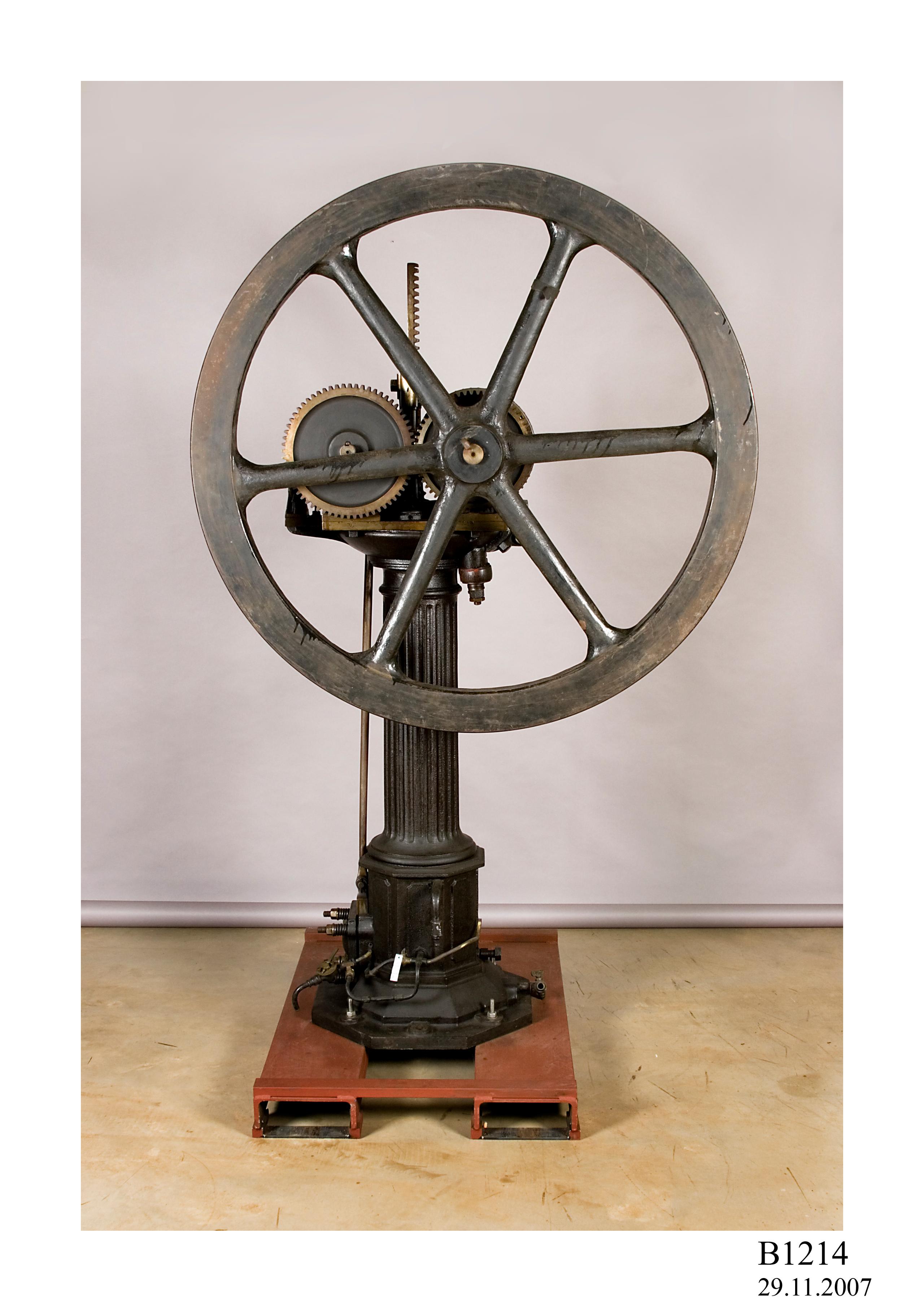
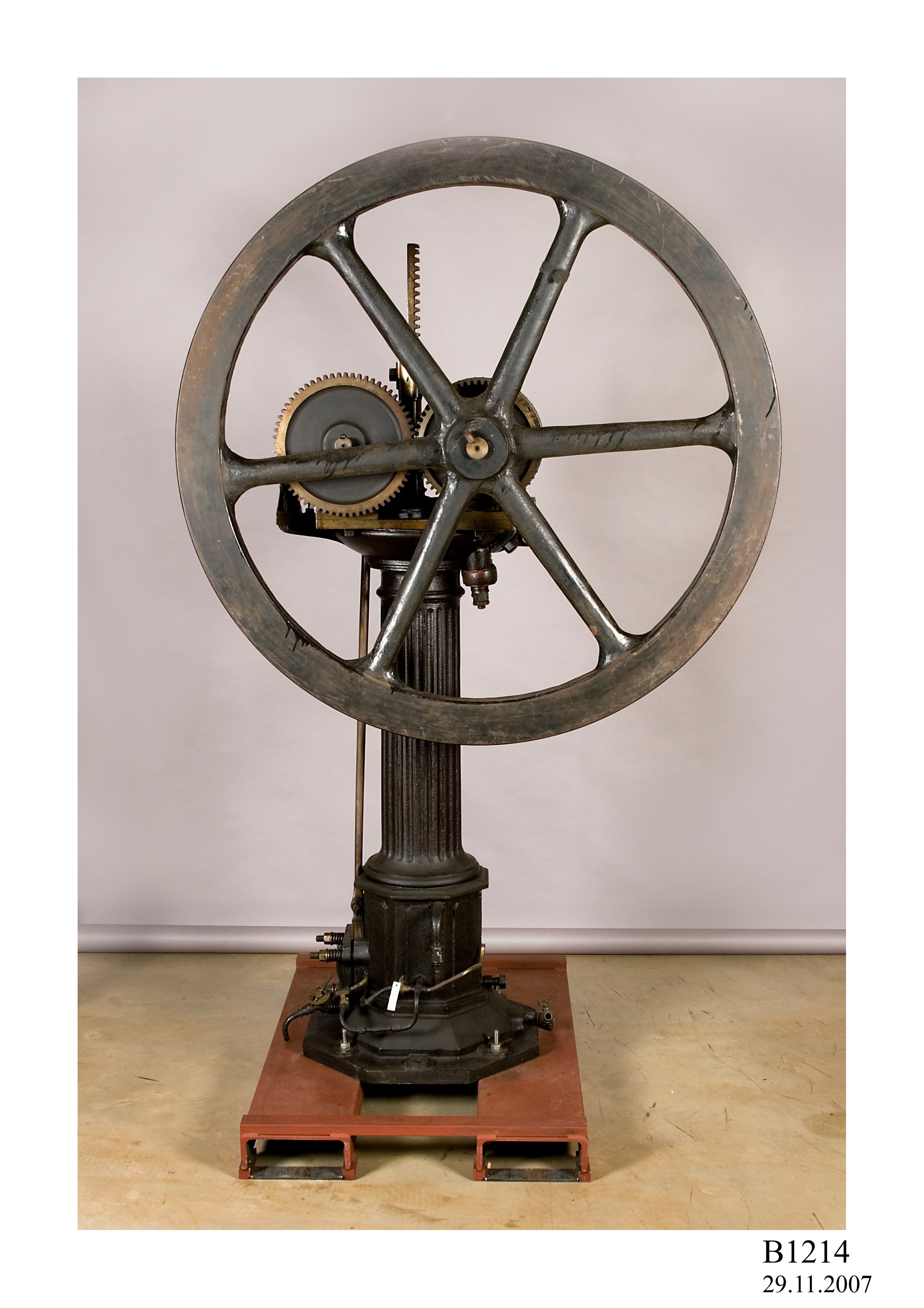
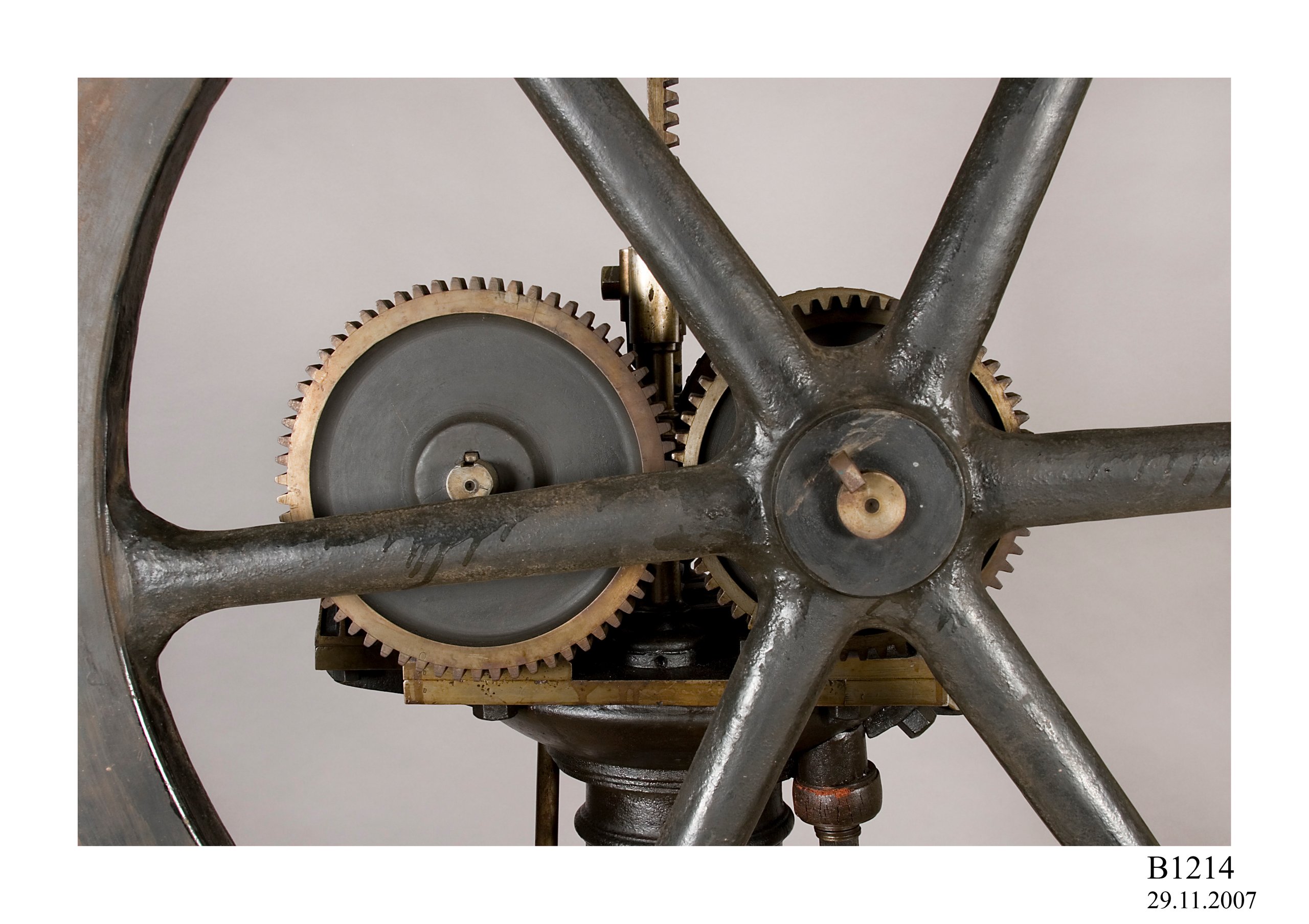
Otto-Langen vertical free piston atmospheric gas engine
Object No. B1214
From the mid 19th century, gas engines were developed as feasible alternatives to steam engines, particularly for small power requirements as in workshops, warehouses, printing works and the food industry. Their development was spurred by the establishment of gasworks and pipelines to deliver coal gas throughout many cities. The Otto-Langen free piston atmospheric gas engine was patented in 1866 and awarded the Grand Prize at the Paris Exposition of 1867 for being the most efficient gas engine ever produced. It became the world's first commercially successful internal combustion engine. About 2650 engines were manufactured in Germany until 1878, when Otto exhibited his silent gas engine at another Paris Exposition. The engine shown at the Paris Exposition in 1867 had a 'Grecian Ionic' column (which was manufactured until 1872) and vertical crosshead guide rods. These guide rod engines were manufactured for only a few years. In the early years, two slide valves were utilised. Earlier engines of this type had not proven successful due to excessive friction and wear on the components; the roller-wedge clutch utilised by Otto is thus regarded as an essential feature of the success of the engine. The engine is most likely to be one of the first ten manufactured by N A Otto & Co and is probably older than most of the remaining ones. Only four of the original Grecian column version are known to have survived, with one being owned by the Smithsonian Institution in Washington DC and another by the Rough and Tumble Engineers Historical Association of Kinzers PA. A major disadvantage of the free piston engine was the noise and vibration when it was running. When the piston shot up after the gas explosion, the recoil force was transmitted directly to the engine foundations. This was so much of a concern that the engine could only be used in ground level installations. References Bryan Donkin Jr, 'Gas, Oil, and Air Engines', Charles Griffin & Co, London, 1894 Sigvard Strandh, 'Machines, an Illustrated History', Rigby, Adelaide, 1979 Wayne Grenning, 'In the Beginning: History of the Otto-Langen Engine', http://members.aol.com/wgrenning3/ottolangenhistory.html University of Nottingham, 'The Otto-Langen free piston atmospheric engine in the Division of Mechanical Engineering, The University of Nottingham', www.nottingham.ac.uk/engines-group/ottolang.htm https://www.youtube.com/watch?v=09cqOUHbmBI Debbie Rudder, Curator, and Noel Svensson, Powerhouse Volunteer
Loading...
Summary
Object Statement
Otto-Langen gas engine, vertical free piston atmospheric, full size stationary engine, cast iron / steel / bronze, made by N A Otto & Co, Cologne, Germany, 1867-1868
Physical Description
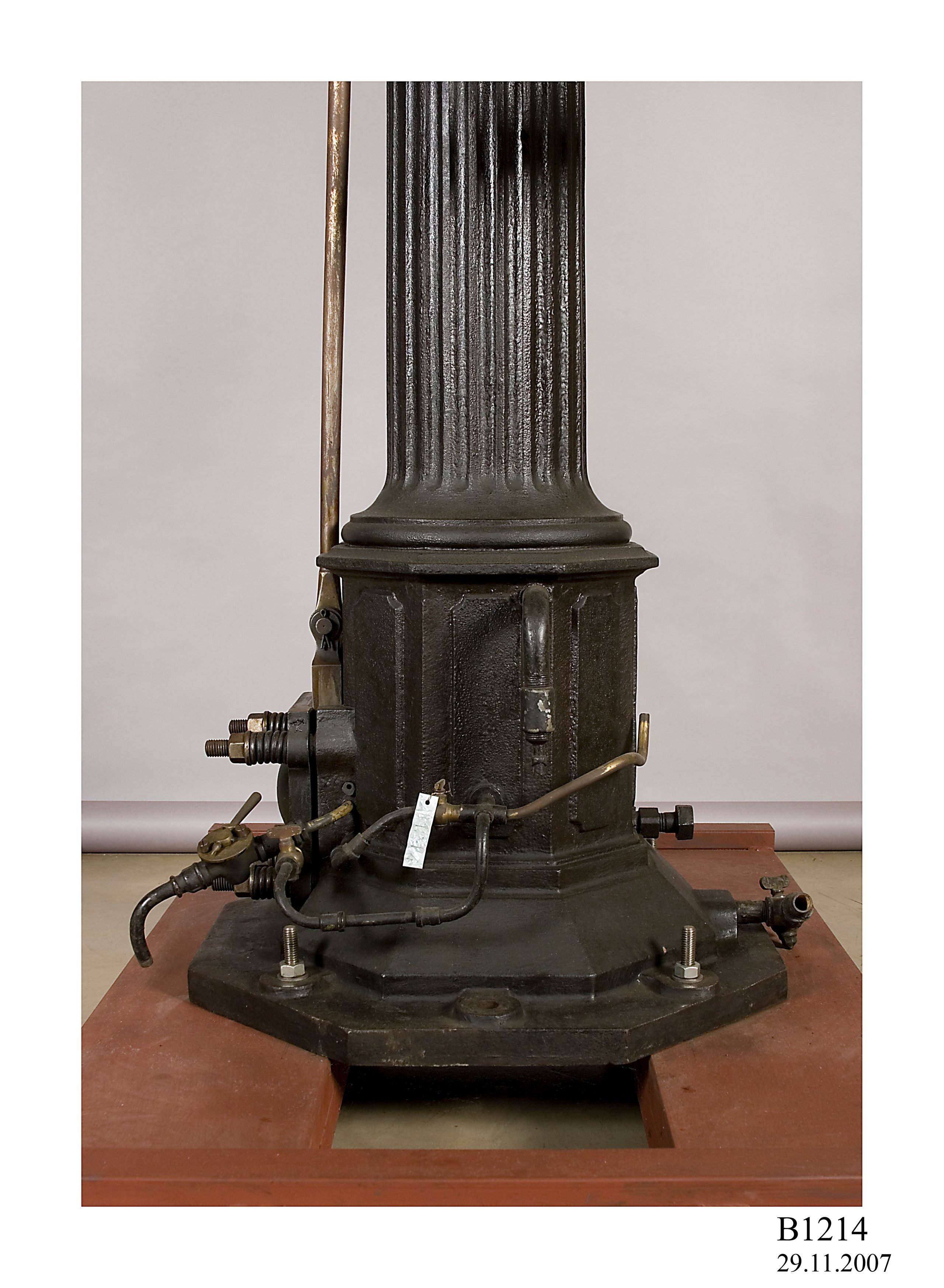
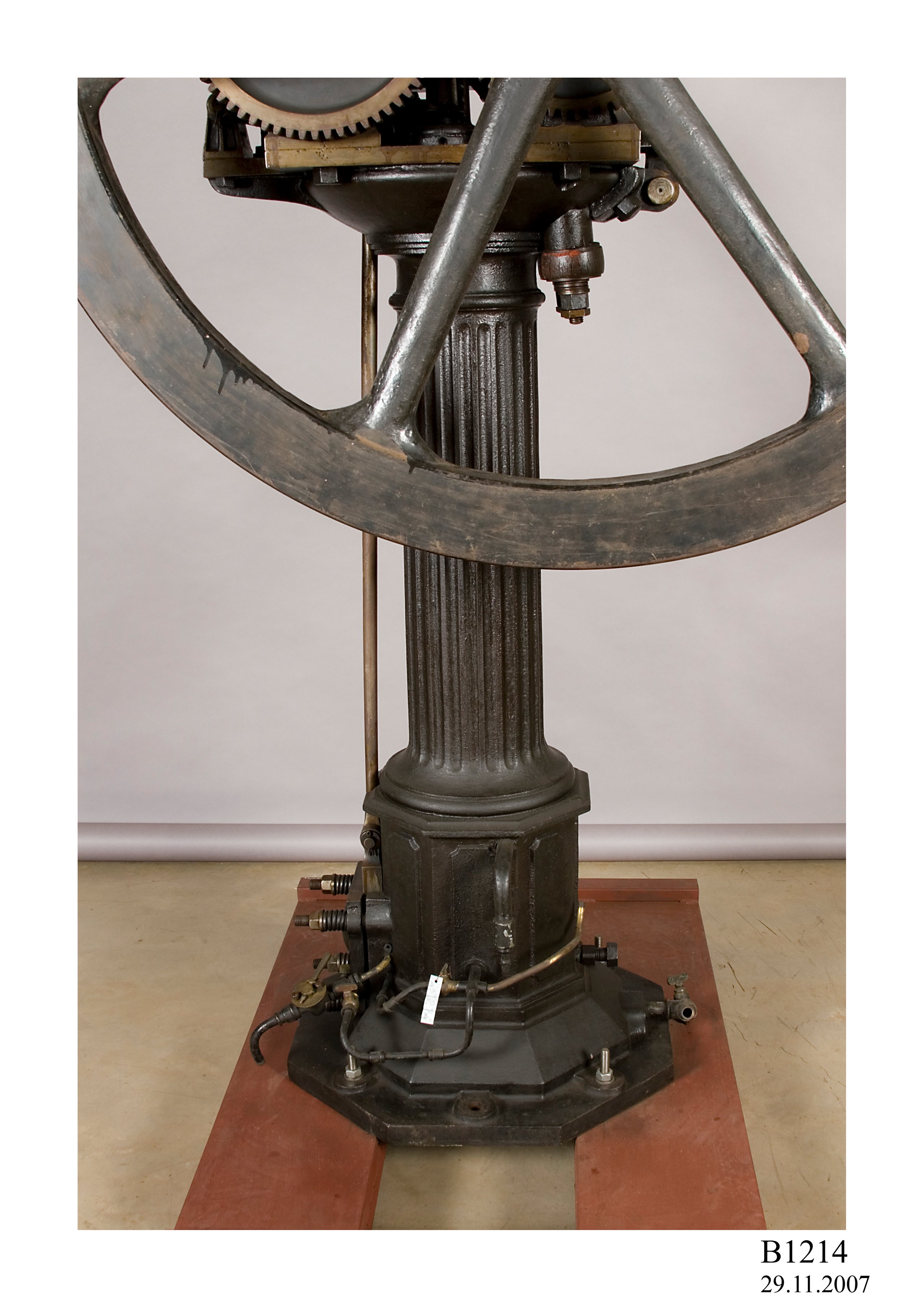
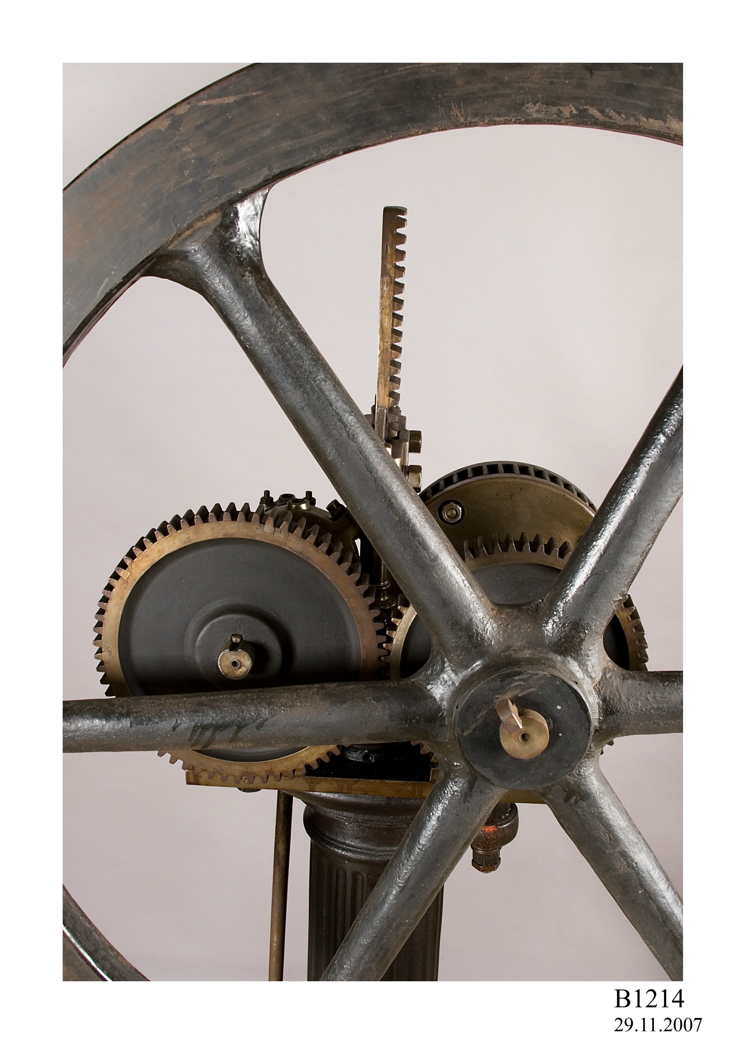
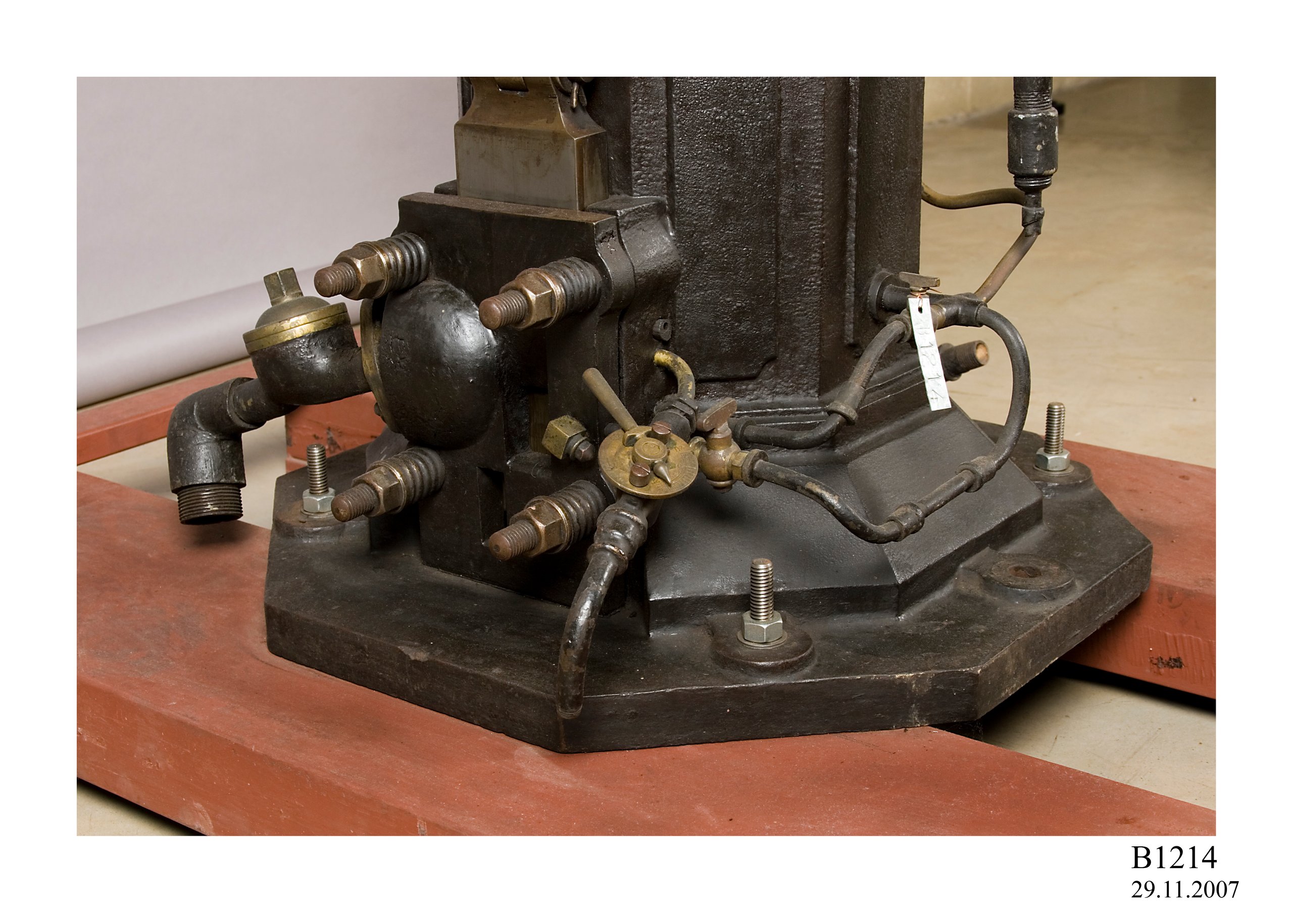
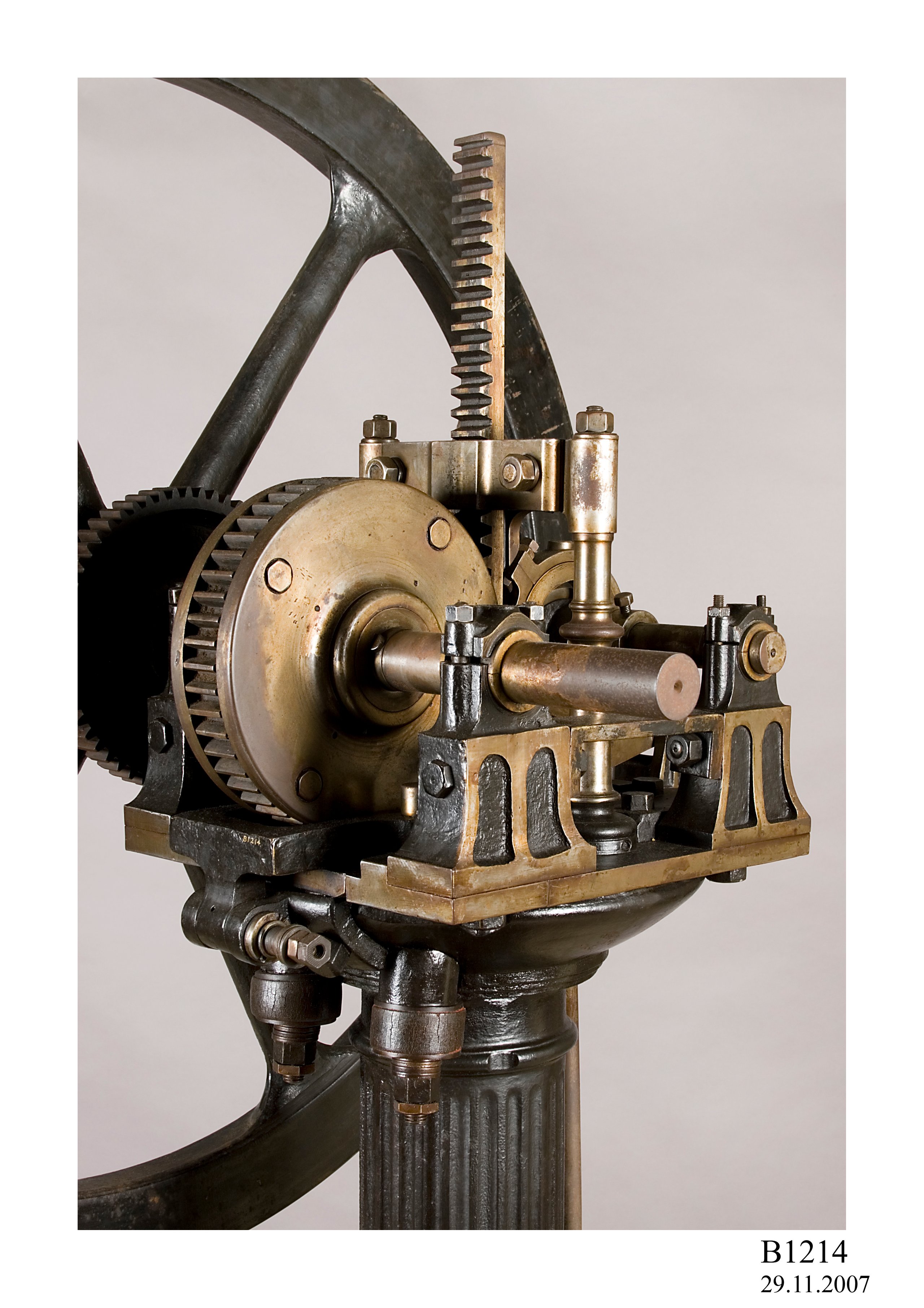
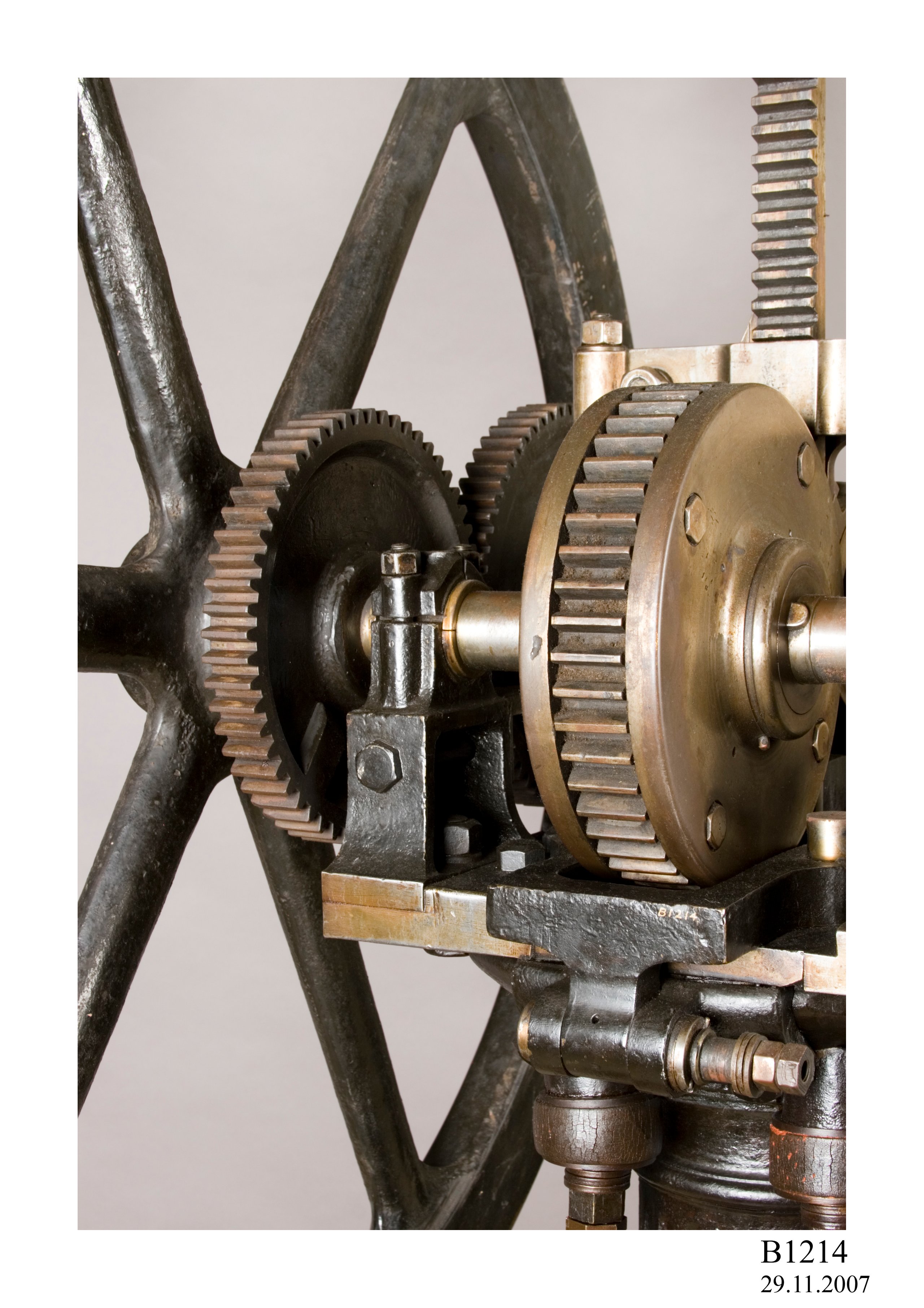
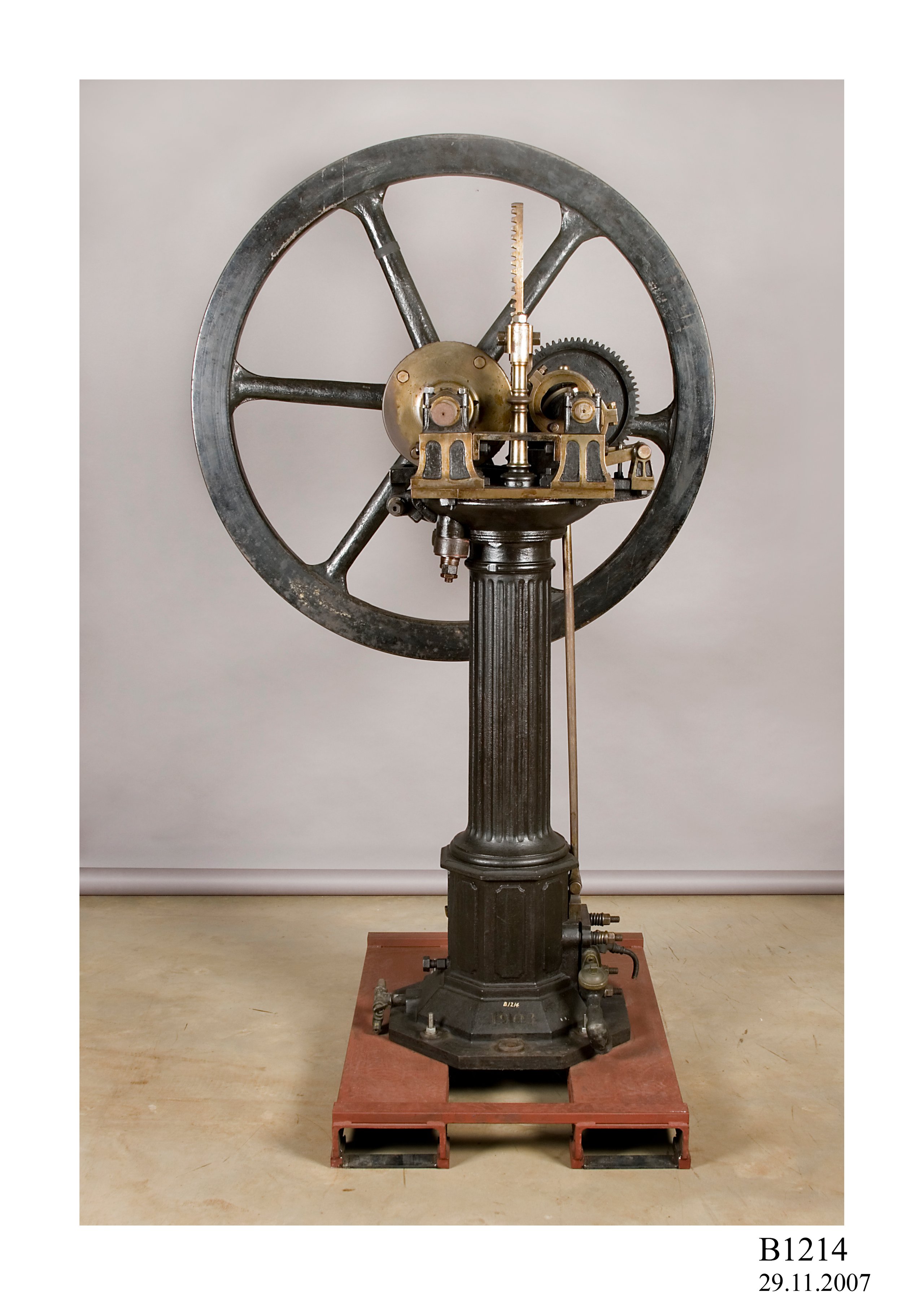
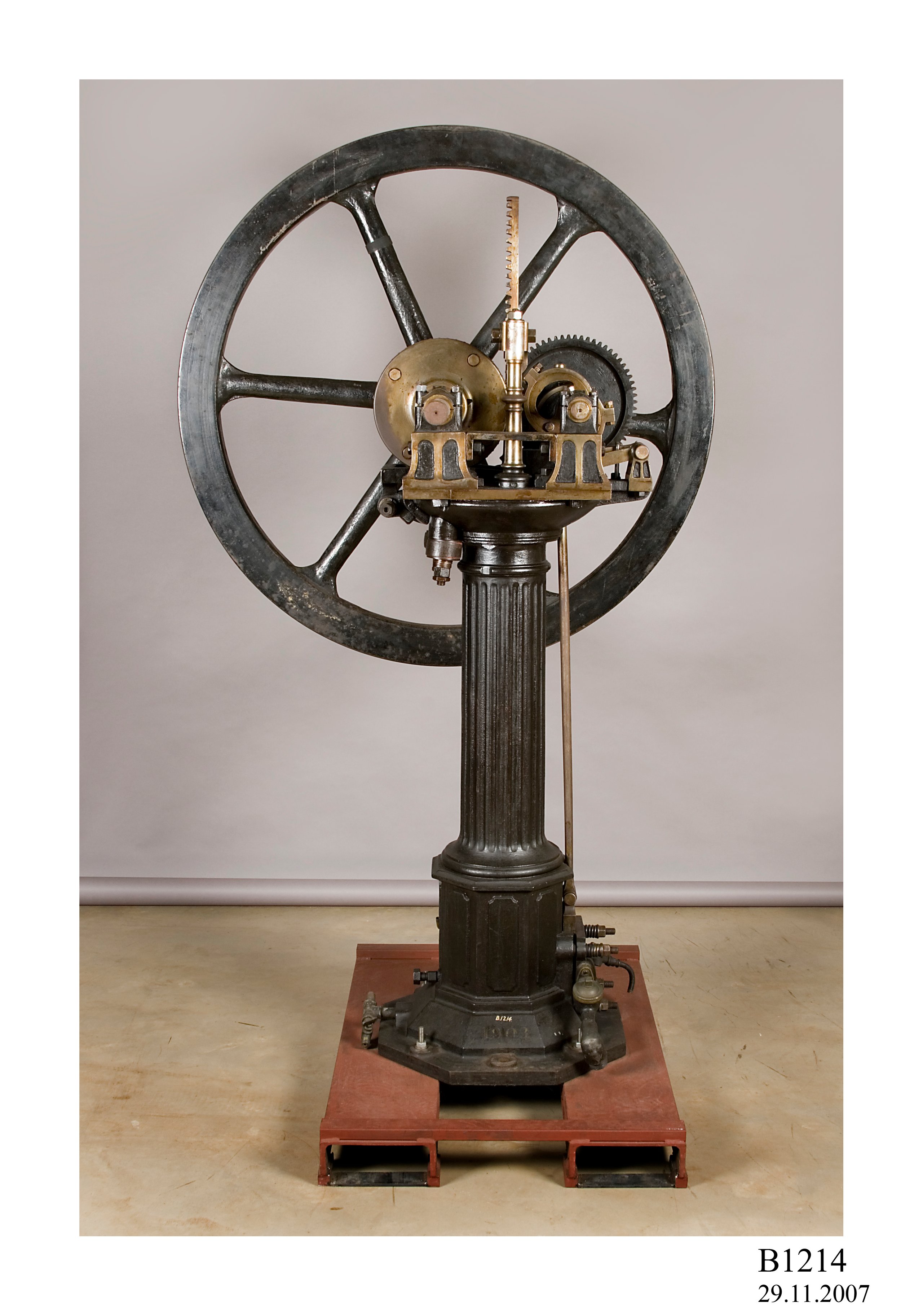
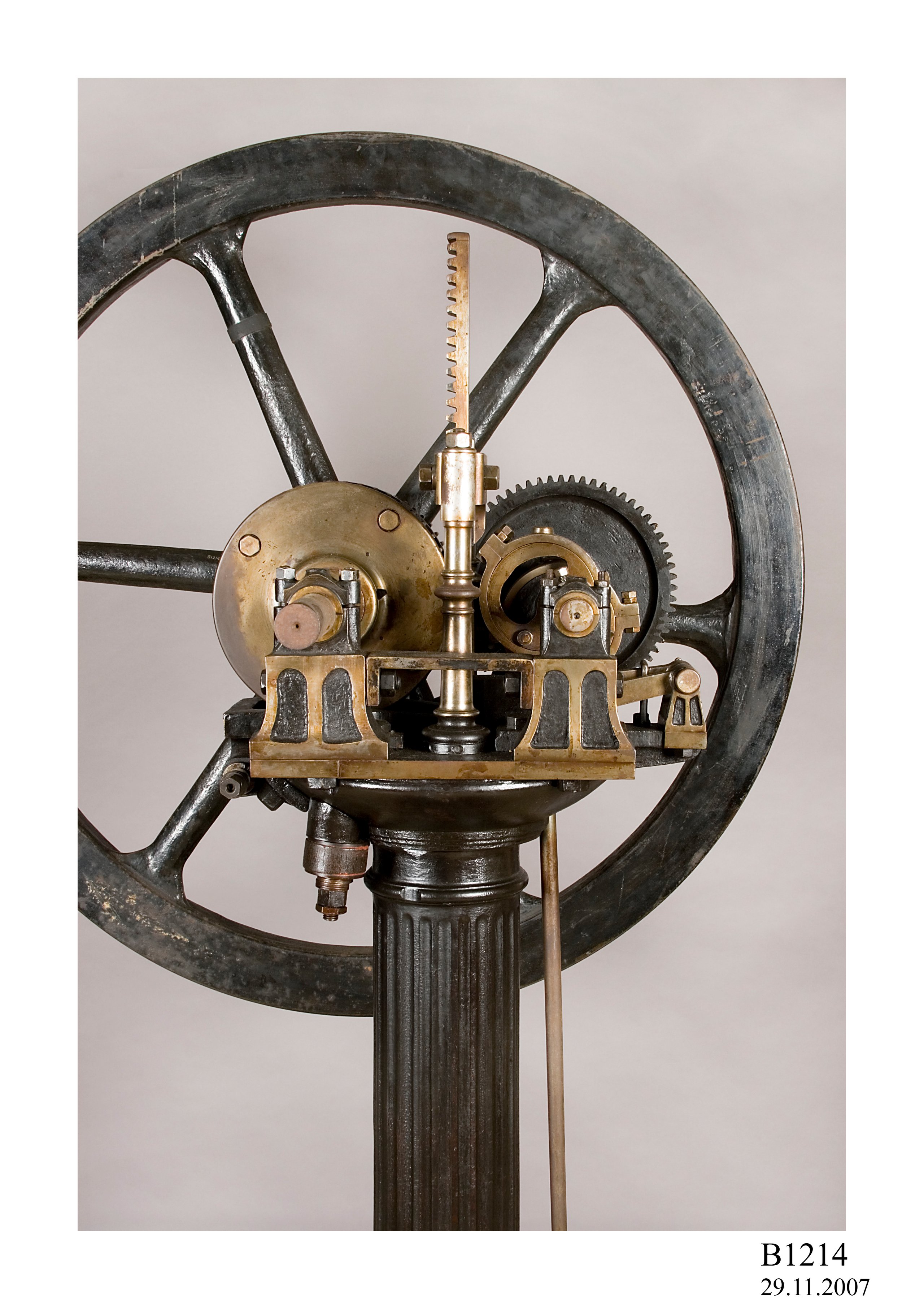
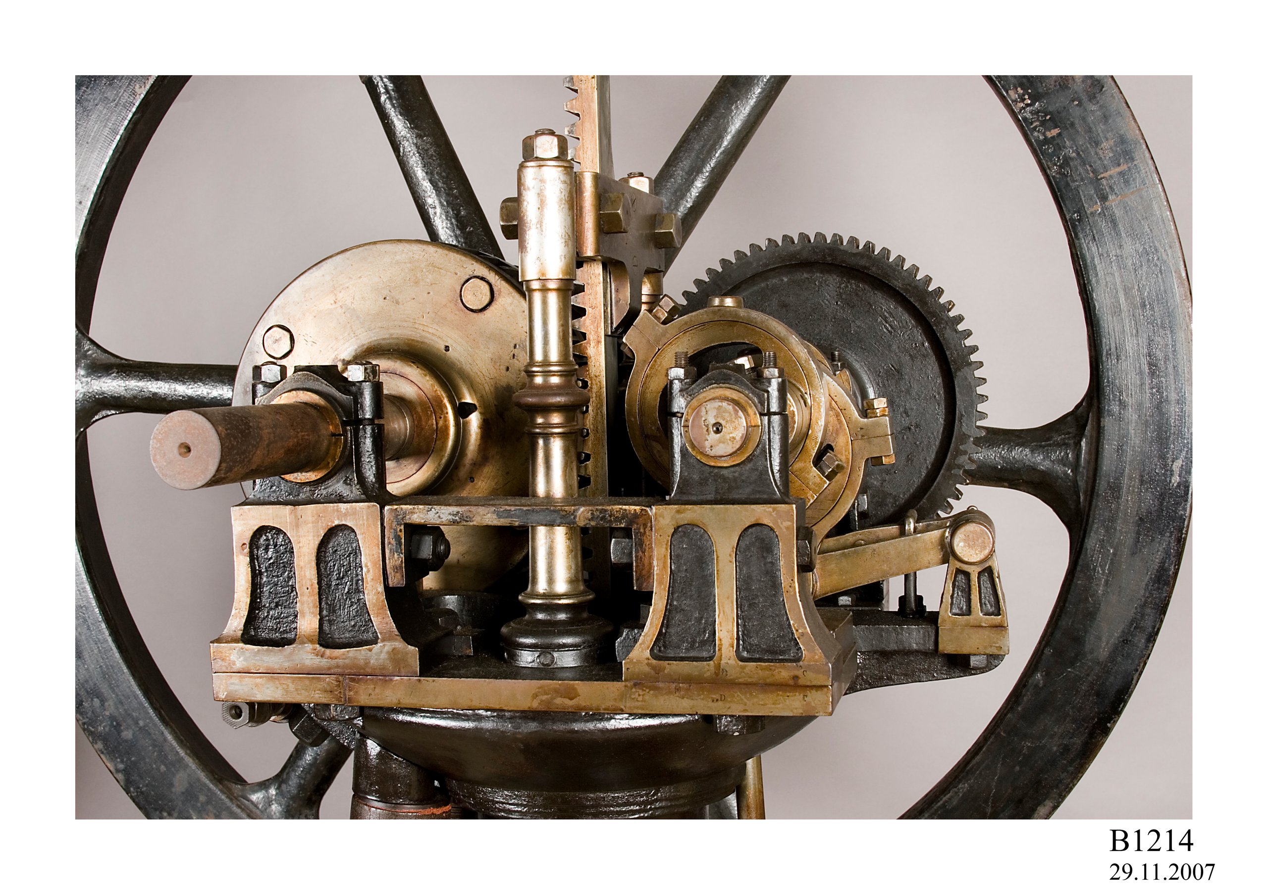
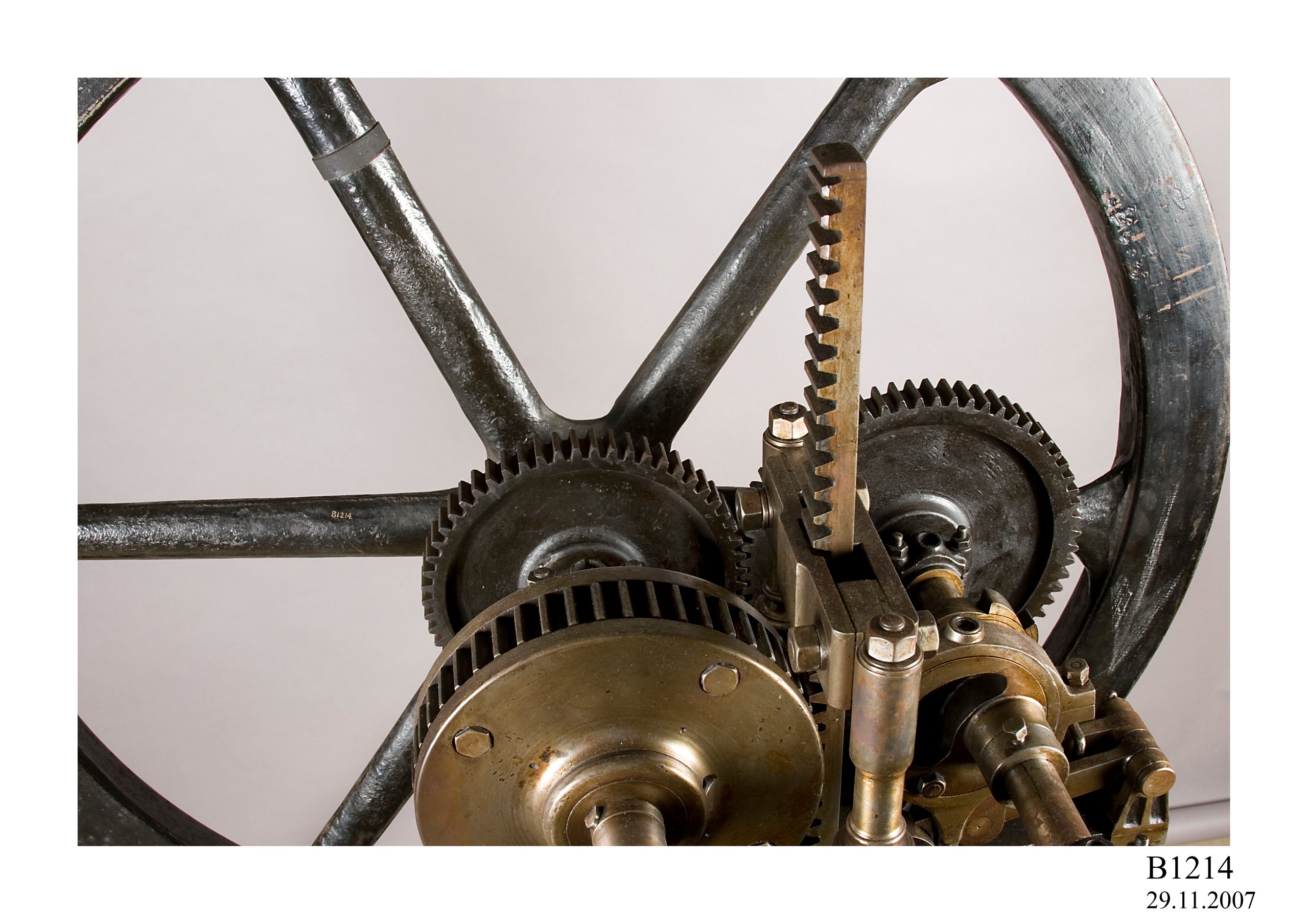
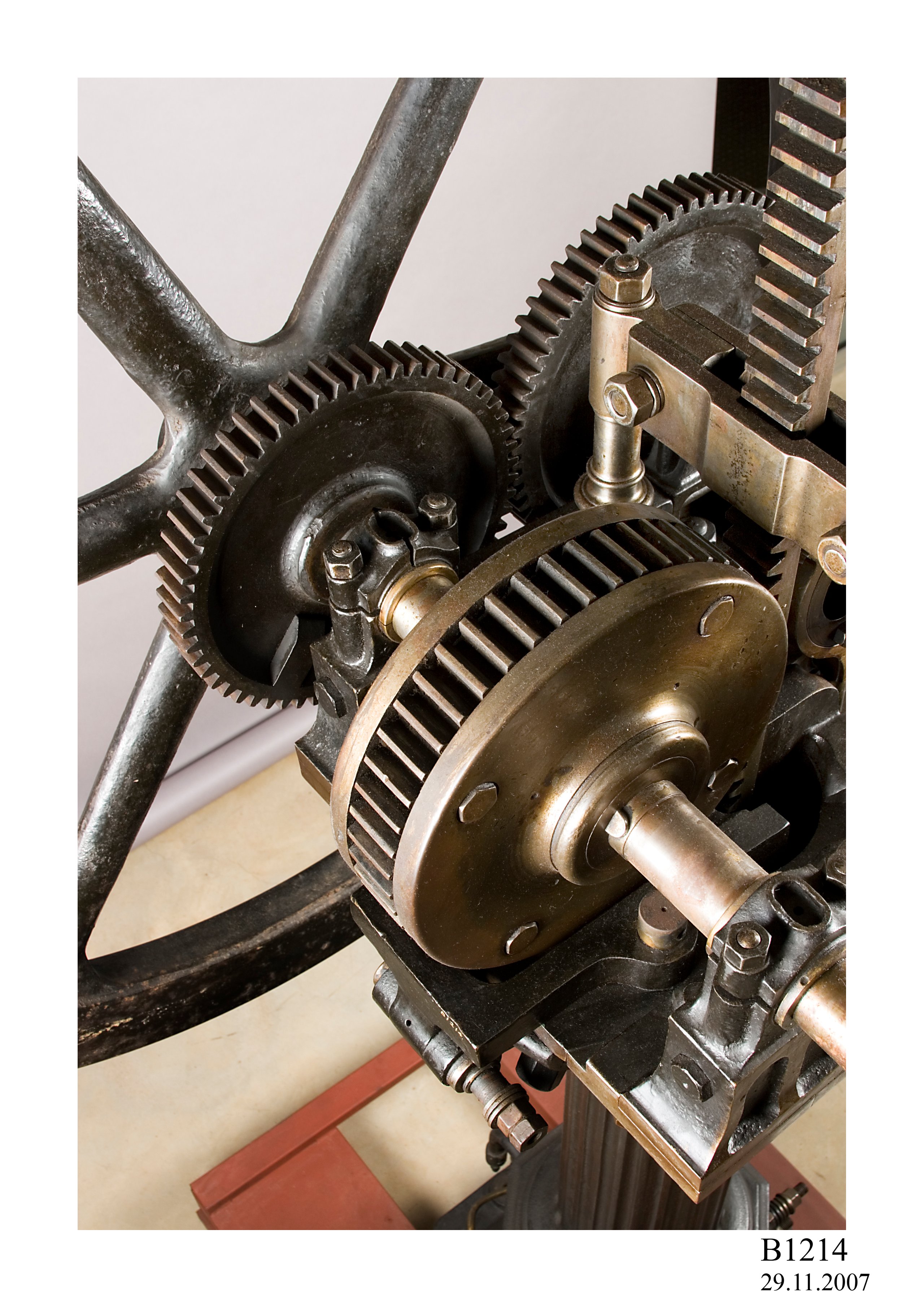
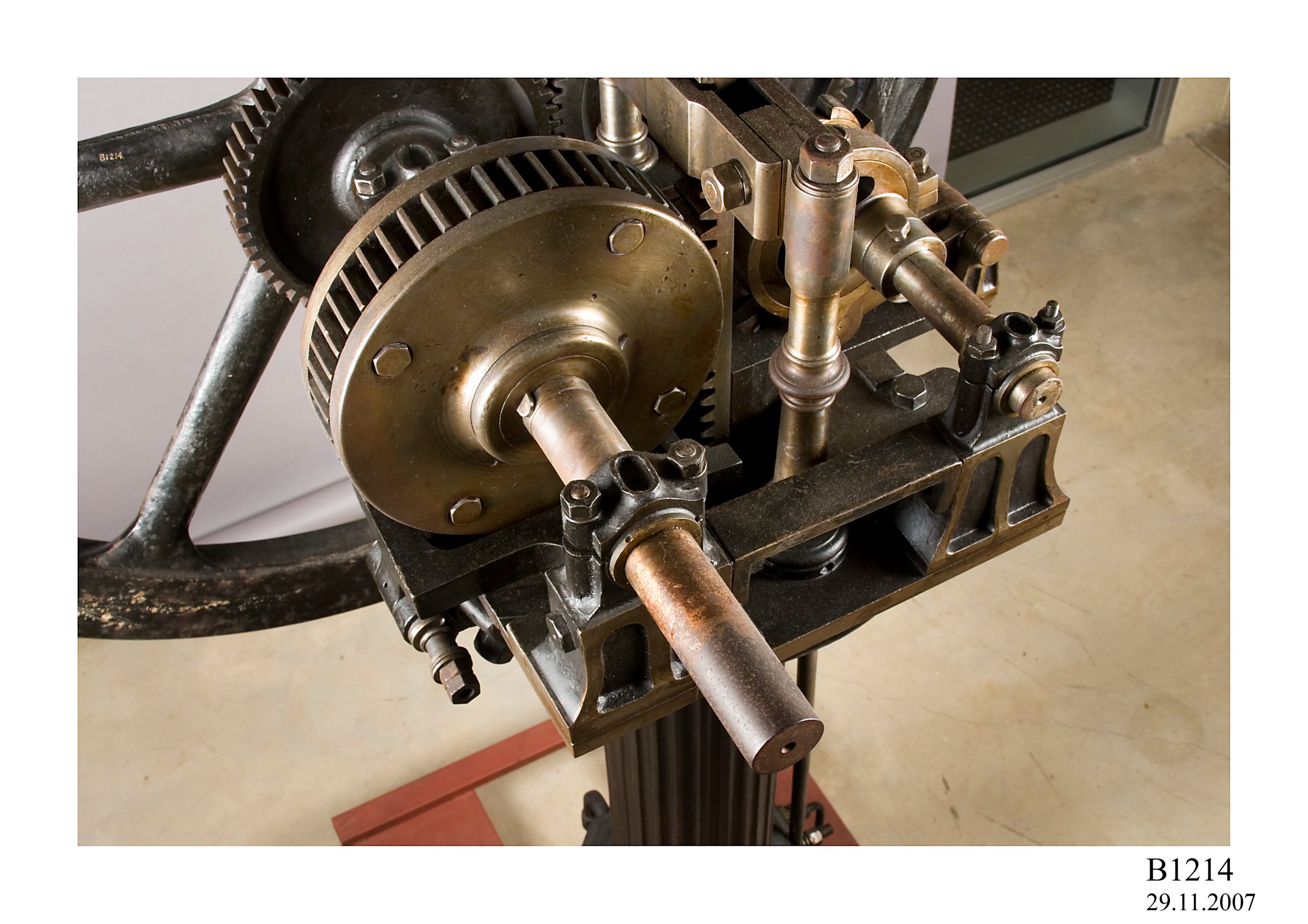
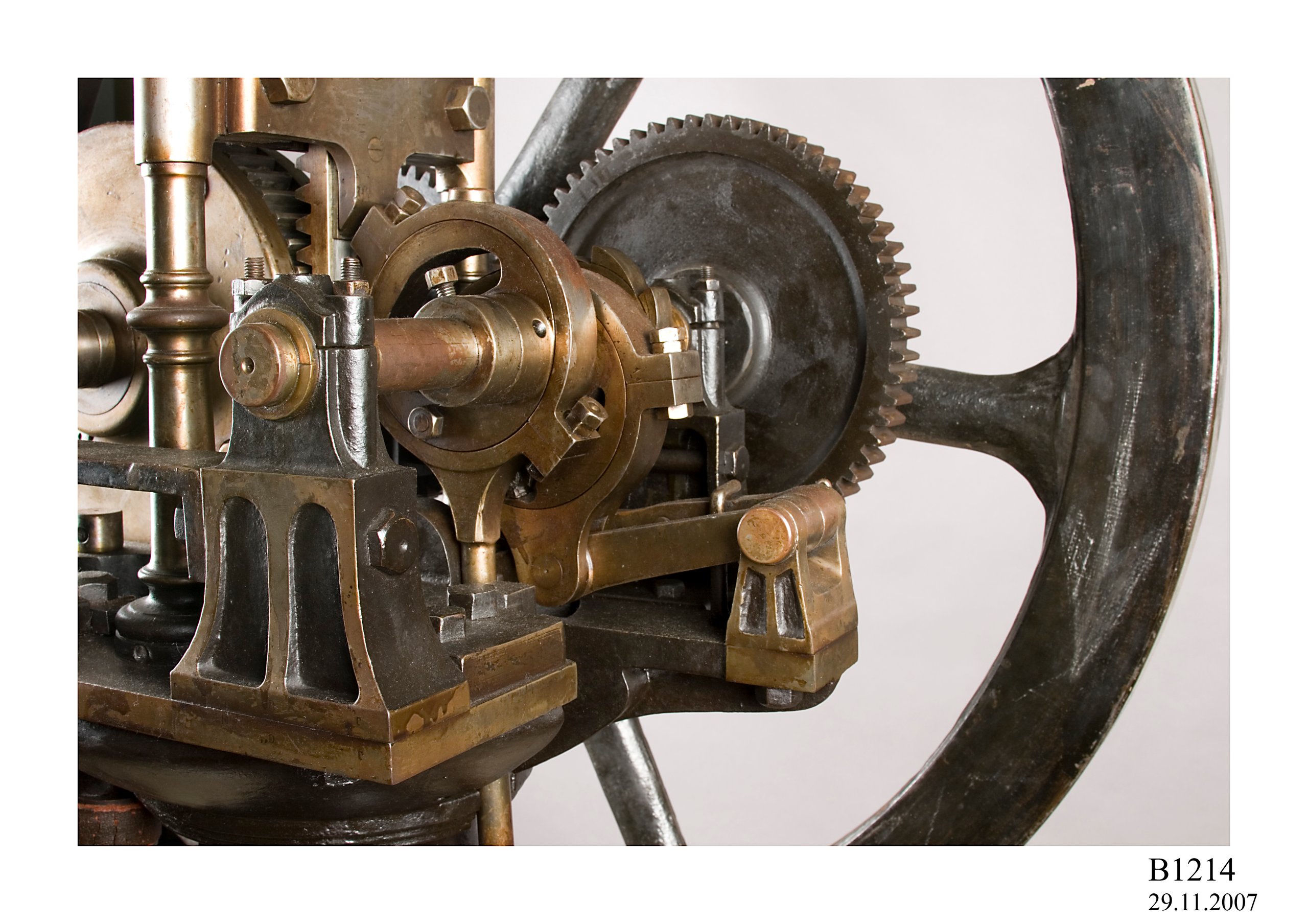
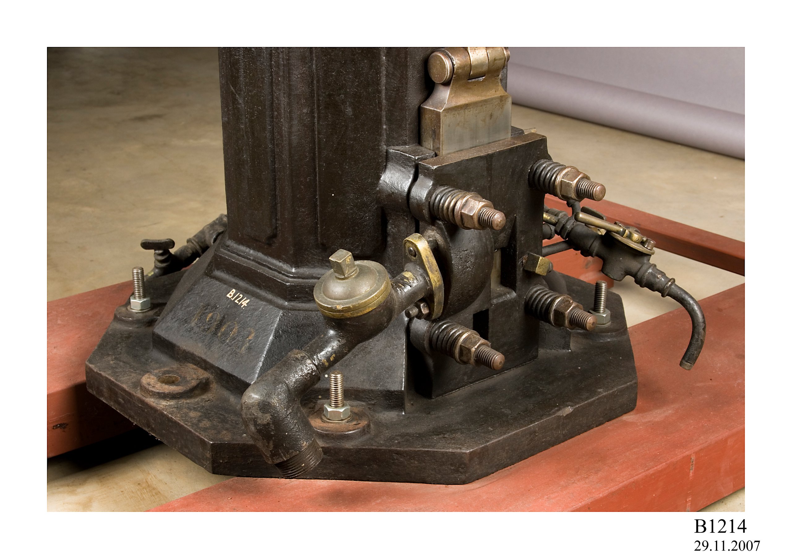
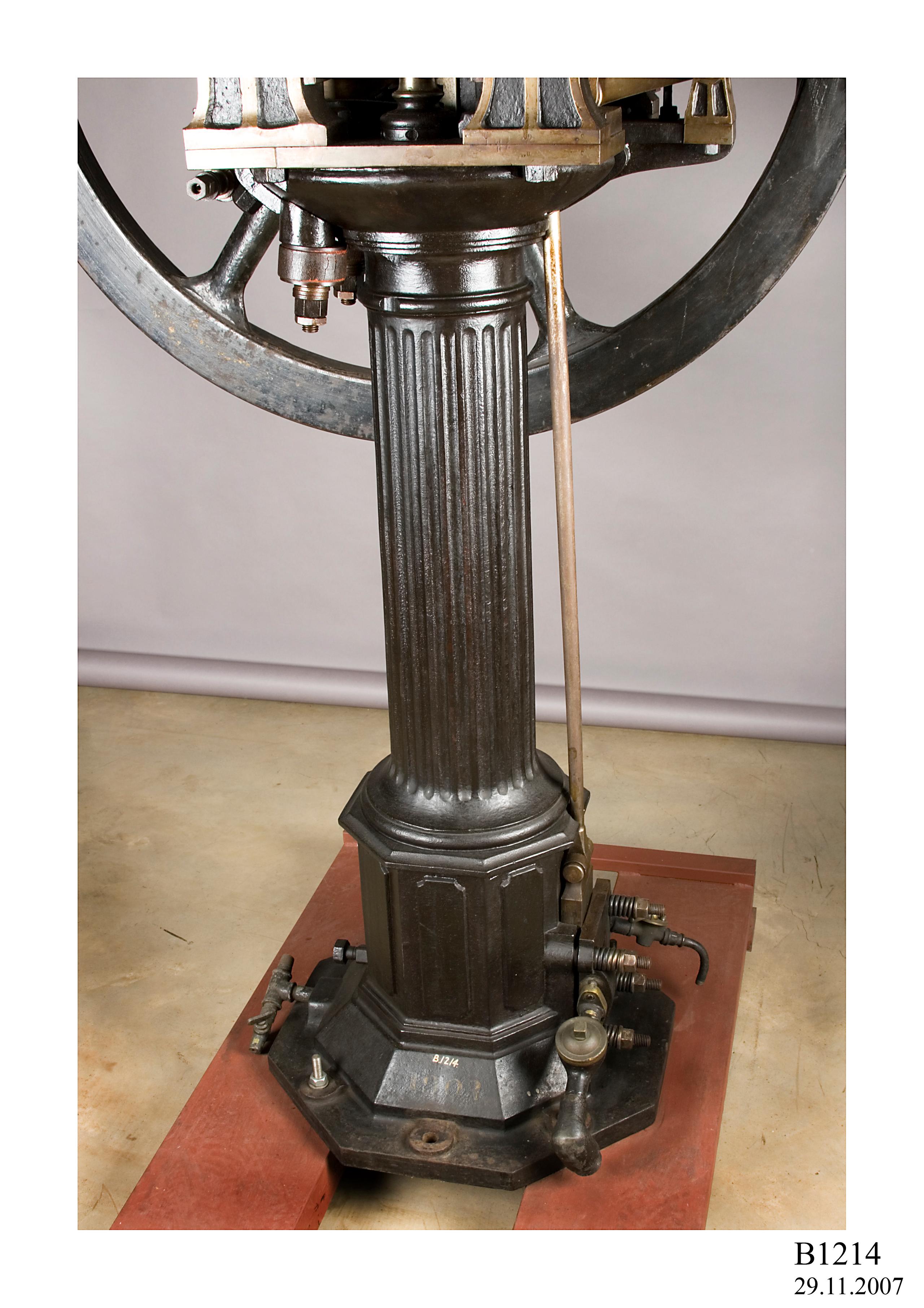
The engine comprises a long vertical cylinder, open to the atmosphere at its upper end, within a fluted column mounted on a pedestal. The appearance of the column is described as Grecian Ionic. At the top of the cylinder are mounted the drive shaft and flywheel. The piston, which is capable of free vertical movement, is attached to a long rack engaging with a spur gear on the drive shaft. The coupling between the spur gear and the drive shaft is achieved through a roller-wedge clutch. In this application the upward motion of the piston in unimpeded but the weight of the piston, some 50 kg, and atmospheric pressure provide the motive force for the engine during the downward movement. The flywheel, required to maintain constancy of speed, dominates the upper end of the engine. The base pedestal incorporates a cooling water jacket at the lower end of the cylinder and the gas inlet valve. A second spur gear on the drive shaft meshes with a similar gear on an auxiliary shaft which has two joined, ratchet-activated, eccentrics which operate to (i) raise the piston and (ii) move the gas inlet slide valve, so that a new charge of the gas-air mixture is admitted to the cylinder when the piston is at the bottom end of the cylinder. This mechanism is activated by a lever, which engages the ratchet, rotating with the auxiliary shaft, which causes the eccentrics to operate so that the movement of the piston and the admission of the charge are correctly timed. The column is made from cast iron, whilst the working parts are made from steel and bronze. Cylinder bore 150 mm, piston stroke 908 mm (max), output 0.5 horsepower (0.37 kW) Operation. When the piston is at the bottom of its stroke it is raised, about 9% of the stroke, by a lever engaging with the rack and operated by an eccentric mounted on the auxiliary shaft. During this time an explosive mix of air and gas is drawn into the cylinder through a slide valve. This mix is then ignited by a flame contained within the slide valve cover. As a result of the explosion the piston is forced upwards until it comes to rest due to the combined influence of gravity and the development of a vacuum in the cylinder. As the piston descends it is connected to the drive shaft through the action of the roller-wedge clutch and so provides the motive force to operate the engine. Exhausting the products of combustion is effected through an exhaust valve. Speed is manually controlled by restricting the gas flow through the exhaust valve; this reduces the speed of descent of the piston, resulting in an increased interval between firing strokes.
PRODUCTION
Notes
The Otto-Langen gas engine was designed and manufactured by Nicolaus Otto and Eugene Langen at their factory, N A Otto & Co, in Cologne, Germany circa 1867. Diesel engine manufacturer Klockner-Humbolt-Deutz AG is the successor to the original firm.
HISTORY
Notes
The engine was made available to the University of Sydney following a visit to the engine works in Cologne by Professor Sir Henry Barraclough. The engine was loaded onto a German freighter before the outbreak of the first World War in 1914. On the outbreak of war the freighter was diverted to Borneo and sheltered there until 1916. Barraclough despaired of ever seeing the engine, which he had wanted to acquire for many years. It was finally installed in the mechanical engineering laboratory at the University of Sydney in the early 1920s and was used there for student experiments. On one occasion, an explosion caused the flywheel to spin off and break, probably as a result of the engine being started when some gas remained in its cylinder from its previous run; the parts of the flywheel were used as a pattern for casting a new one. The University donated the engine to the Museum in 1954. At the 1867 Paris Exposition, tests on a half-horsepower engine at a speed of 81 rpm recorded a lighting (coal) gas consumption of 44 cu ft/hp hr (1670 L/kW hr). Tests at the University of Sydney showed that at a speed of 262 rpm, piston stroke rate of 164/min, the engine developed 0.51 horsepower (0.38 kW) with gas consumption of 3861 L/kW hr (indicated) and a mechanical efficiency of 68.3%.
SOURCE
Credit Line
Gift of the University of Sydney, 1954
Acquisition Date
1 March 1954

Copyright for the above image is held by the Powerhouse and may be subject to third-party copyright restrictions. Please submit an Image Licensing Enquiry for information regarding reproduction, copyright and fees. Text is released under Attribution-Non Commercial-No Derivative licence.
Image Licensing Enquiry
Object Enquiry